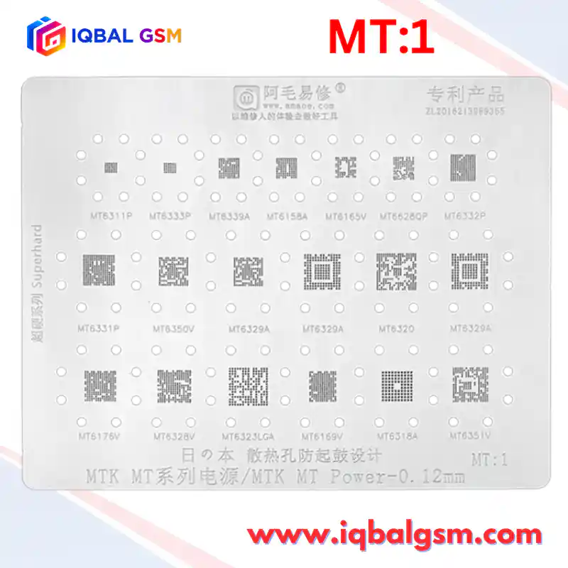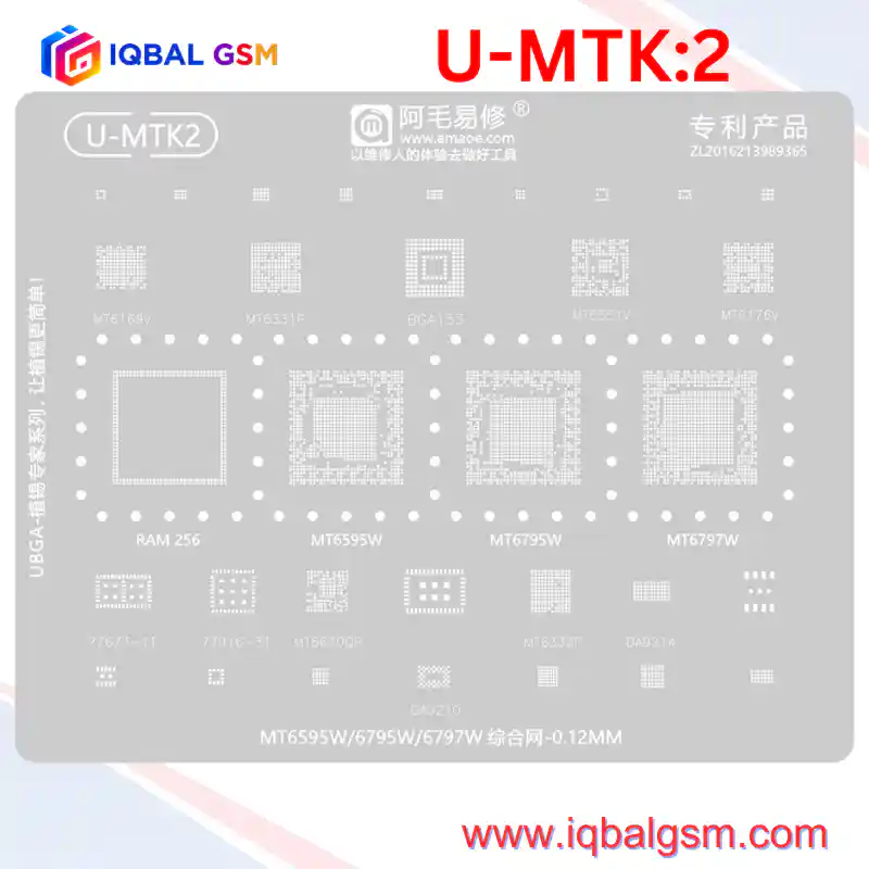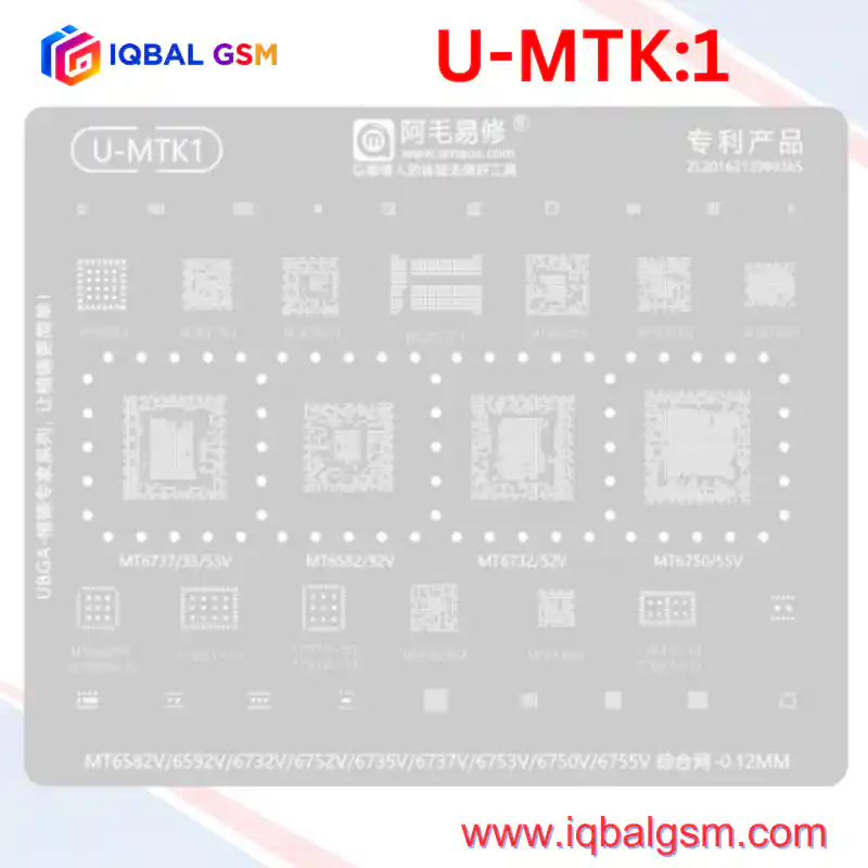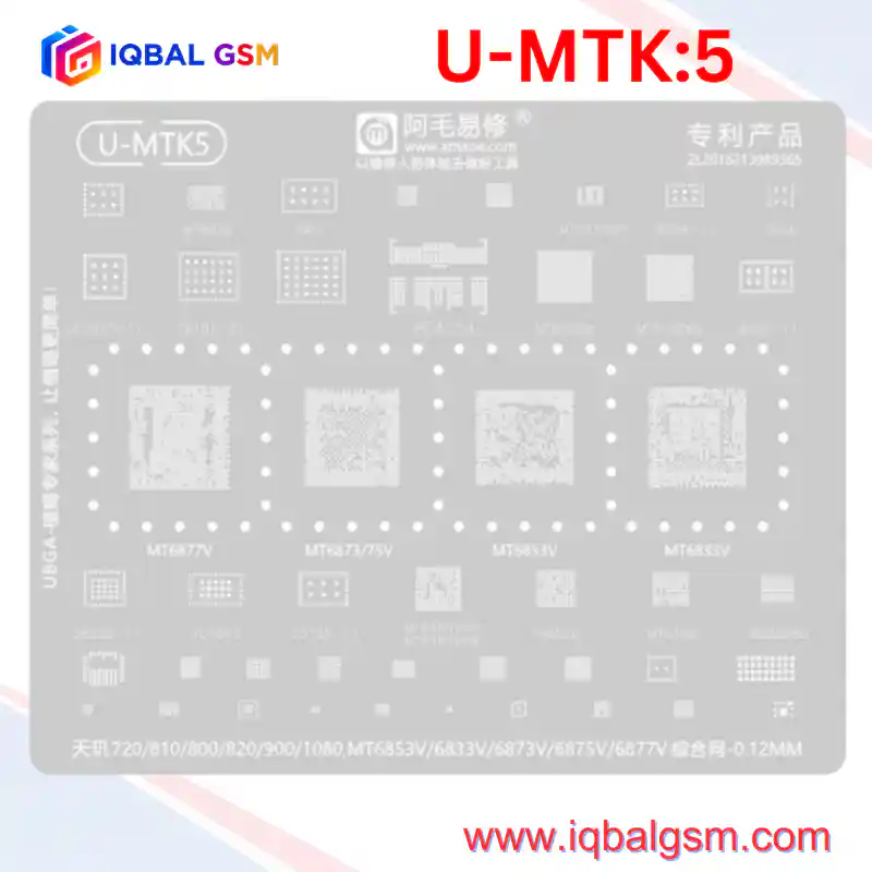

U-MTK 8
As low as
Rs 700.00
Worldwide shipping · Cash on Delivery
Product Details
================================================================================
1. 2nd-GEN 4nm SILICON TOPOLOGY & THERMAL ANALYSIS (DIMENSITY 7200 / 7300)
================================================================================
The AMAOE U-MTK8 stencil is dedicated to MediaTek's advanced TSMC 4nm (N4P) Dimensity
silicon architecture, featuring ARMv9 Cortex-A715 cores, Mali-G615 graphics, and fine-pitch
0.35 mm BGA substrates:
A. DIMENSITY 7200 (MT6886V) & DIMENSITY 7300 (MT6878V) APPLICATION PROCESSORS:
- Fabrication & Die: TSMC 4nm FinFET process with high thermal and power density.
- Ball Pitch & Substrate Design: Ultra-fine 0.35 mm pitch with center decoupling keep-outs.
- Substrate Vulnerability: The 4nm silicon die generates localized hot spots around the dual
Cortex-A715 cluster under heavy camera computational photography (e.g., 200MP sensor processing
on Redmi Note 13 Pro+ / Note 14 Pro). Solder fatigue frequently develops across the central
VPROC power balls and surrounding ground array.
- Fault Symptoms: Sudden device shutdown during 4K video recording, bootlooping at the vendor splash
screen, or failure to wake from deep sleep with the device dropping into MTK USB BROM mode.
B. POWER TREE ARCHITECTURE (MT6377W + MT6368CW + MT6360PP):
- Primary 5G System PMIC (MT6377W):
* The master power management unit tailored specifically for MT6886 and MT6878 platforms.
* Generates high-efficiency buck supplies for VPROC (0.6V - 0.95V dynamic voltage scaling),
VCORE, VGPU, VMODEM, 1.8V system I/O (VIO18), and powers the 26 MHz system master crystal.
* Failure Mode: If MT6377W suffers cracked corner solder joints from drops, the device will pull
30 mA - 55 mA upon pressing the power button and hang indefinitely without releasing RESETB.
- Companion Sub-PMICs (MT6368CW & MT6363CW):
* Synchronous auxiliary step-down converters supporting secondary dynamic CPU and memory rails.
- Charging & USB Management (MT6360PP):
* WLCSP package handling USB Type-C CC/PD negotiation, battery charging, and display bias.
Charger voltage surges over 20V frequently short MT6360PP, pulling the main VSYS rail down to 0V.
C. 5G RF TRANSCEIVER & MEMORY NETWORKS:
- MT6197W: MediaTek's Sub-6GHz FR1 transceiver. Solder bridging beneath MT6197W results in
complete modem baseband failure (IMEI null or baseband version showing "Unknown").
- BGA254 / BGA200 / BGA153:
* High-speed UFS 3.1 storage lines operate at multi-gigabit rates; coplanar solder ball height
is essential to prevent data line reflection and corrupt preloader handshakes.
================================================================================
2. SOLDER PASTE & THERMAL GRADIENT SPECIFICATIONS
================================================================================
- Stencil Thickness: 0.12 mm precision laser-cut hardened Japanese stainless steel.
- Solder Paste Alloy Selection:
* Sn63/Pb37 (63% Tin / 37% Lead) Eutectic Alloy: Melting Point 183°C.
* Solder Powder Particle Size: Type 4 (20 - 38 microns) or Type 5 (15 - 25 microns) is MANDATORY.
Using Type 3 paste on the 0.35 mm pitch of MT6886V will cause severe paste bridging across apertures.
* Flux Formulation: High-viscosity No-Clean or Rosin Mildly Activated (RMA) tacky paste flux.
- Working Temperatures:
* Stencil Ball Reflow: 310°C - 325°C hot air, 25% - 30% airflow.
* Motherboard Desoldering: 350°C - 365°C (with bottom preheater at 145°C - 160°C).
* Motherboard Installation / Reflow: 335°C - 350°C until self-alignment occurs.
================================================================================
3. ADVANCED 4nm BGA REWORK & REBALLING WORKFLOW
================================================================================
STEP 1: PRE-HEATING & CHIP EXTRACTION
1. Mount the motherboard in a high-mass CNC logic board fixture. Mask surrounding plastic FPC
connectors, SIM trays, and optical camera modules with dual-layer aluminum heat-deflector tape.
2. Bottom Pre-Heat: Set bottom preheater to 150°C - 160°C across the board underside.
3. Apply tacky flux around the perimeter of the Dimensity SoC (MT6886V/MT6878V) or PMIC (MT6377W).
4. Set hot-air wand to 355°C - 365°C with an 8 mm or 10 mm circular nozzle (airflow 45%).
5. Heat in smooth, continuous rectangular motions 1.5 cm above the chip for 35-45 seconds.
6. Verify solder liquefaction by nudging an adjacent surface-mount capacitor. Lift the chip straight
up using precision vacuum tweezers or ultra-fine curved tweezers (#5). Avoid any lateral prying.
STEP 2: PAD RESURFACING & EPOXY REMOVAL
1. Lower hot air to 250°C. Apply moderate RMA flux and gently scrape softened black underfill glue
from the PCB pads and IC package margins using a non-scratch copper scraper blade.
2. Tin the footprint pads with 183°C leaded solder using a 330°C micro-soldering iron (C210-K knife tip).
3. Lay high-purity copper desoldering wick across the pads and glide the flat iron face across the
wick without applying downward pressure.
4. Level the IC base pads until smooth and planar. Clean with 99.9% IPA until mirror-clean.
STEP 3: REBALLING WITH THE AMAOE U-MTK8 STENCIL
1. Seat the cleaned IC into a magnetic reballing fixture.
2. Position the corresponding aperture on the U-MTK8 stencil:
- For Dimensity 7200, align with MT6886V.
- For Dimensity 7300, align with MT6878V.
- For Dimensity 6100+, align with MT6835V.
- For Helio G96, align with MT6781V.
- For power ICs, align with MT6377W, MT6368CW, or MT6360PP.
3. Verify that the circular anti-bulging expansion holes surround the chip perimeter to prevent
stencil warping under heat.
4. Spread Sn63/Pb37 paste into the apertures at a 45° angle with a flexible steel spatula. Wipe the
surface 100% clean of excess solder beads.
5. Hold the stencil down firmly at the margins with bent-tip titanium tweezers.
6. Direct hot air at 310°C - 325°C (airflow 25% - 30%) 3 cm above the stencil, moving inward.
Observe the paste coalesce into uniform spherical balls.
7. Allow 8-10 seconds to cool and solidify before lifting the stencil vertically.
8. Apply a drop of liquid flux and pass hot air for 3 seconds at 300°C for final spherical centering.
STEP 4: MOTHERBOARD INSTALLATION
1. Spread a micro-thin layer of tacky flux across the PCB pads (shiny, not flooded).
2. Align the IC with the PCB silkscreen corner brackets (verify Pin 1 dot orientation).
3. Reflow with hot air at 340°C - 350°C (airflow 40%). When the solder melts, surface tension will pull
the IC into exact alignment. Give a gentle 0.1 mm tweezer nudge: the chip must snap back immediately.
================================================================================
4. ELECTRICAL DIAGNOSTICS & FAULT MATRIX
================================================================================
1. Diode-Mode Impedance Verification (Unpowered board, Red probe to GND, Black probe to test point):
- VPROC / VCORE Buck Coils (MT6377W) : 0.015 V - 0.050 V (Normal low-impedance buck loop).
- VIO18 (1.8V System I/O Rail) : 0.380 V - 0.490 V (Short indicates PMIC/SoC bridge).
- VSYS / VBAT (Primary Battery Rail) : 0.420 V - 0.540 V (Short < 0.050 V indicates blown MT6360PP).
- LPDDR4X / LPDDR5 VDD1 / VDD2 : 0.260 V - 0.390 V.
2. DC Power Supply Boot-Up Analysis (4.0V DC Input on VBAT):
- 0.000 A Standby: Normal prior to pressing Power button.
- 20 mA - 80 mA Leakage (Pre-Power): Blown high-side buck MOSFET inside MT6360PP or shorted TVS diode.
- Press Power -> Fixed 30 mA - 55 mA: MT6377W has powered on, but 26 MHz master clock is missing,
or RESETB line is held low by the CPU.
- Press Power -> Cycles 70 mA -> 140 mA -> Drops to 0 mA: CPU has initialized; BGA254 uMCP storage
is unseated, unpowered, or missing firmware communication. Reball the BGA254 chip.
- Normal Boot Progression: Steps steadily from 90 mA -> 300 mA -> 700 mA -> 1.3 A+ into Android OS.