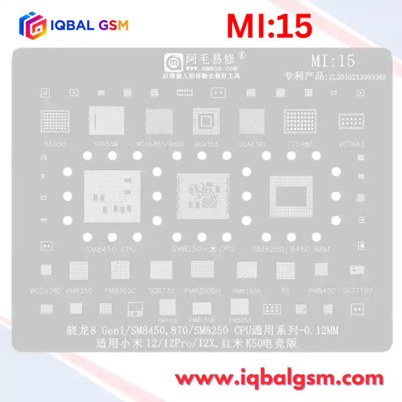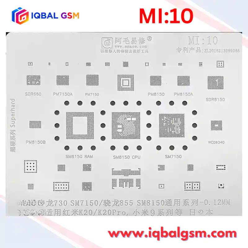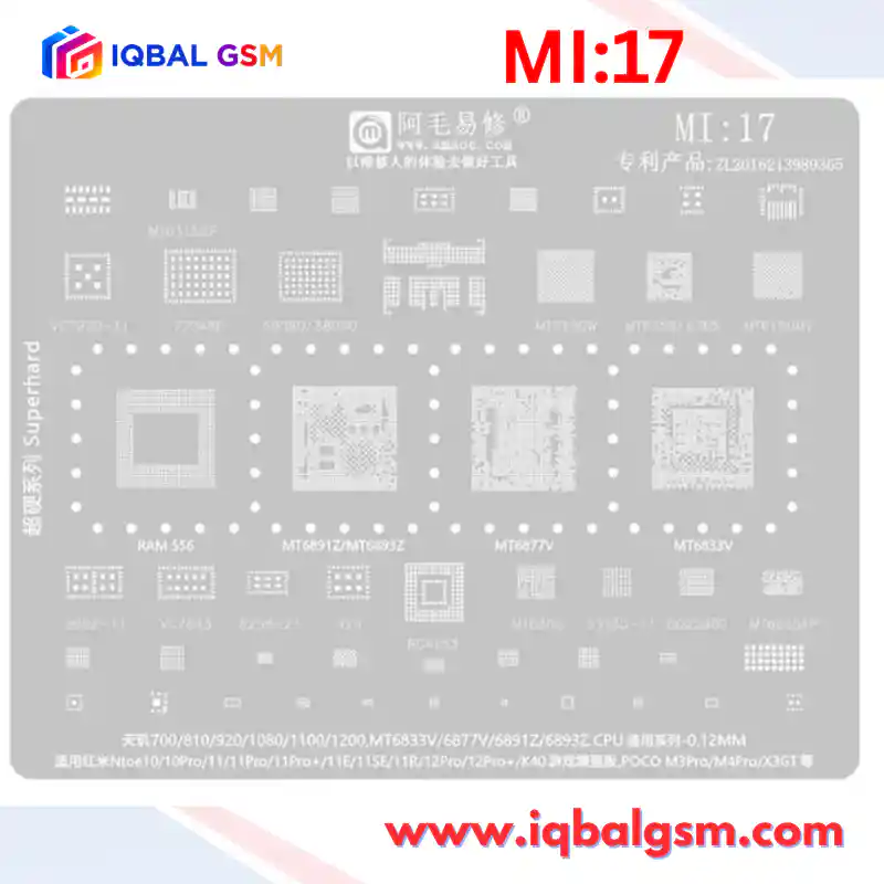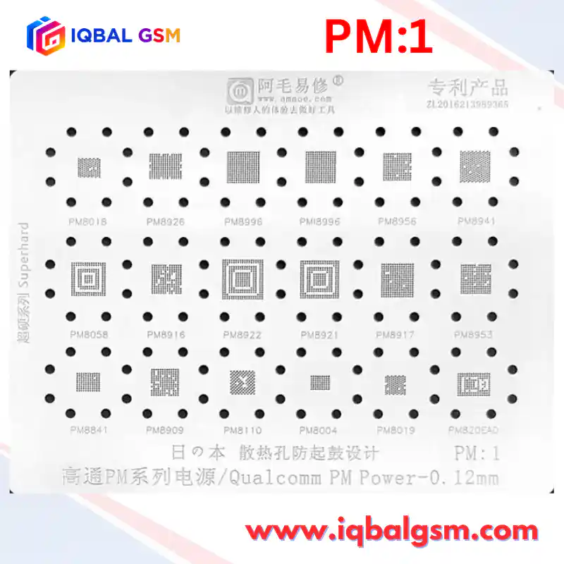

MI-14
As low as
Rs 700.00
Worldwide shipping · Cash on Delivery
Product Details
================================================================================
1. CHIP-LEVEL HARDWARE ARCHITECTURE & SILICON TOPOLOGY (QUALCOMM SM8350)
================================================================================
The AMAOE MI:14 stencil targets Qualcomm's 5nm Snapdragon 888 (SM8350) platform, which
is widely recognized in the mobile repair industry for severe thermal cycling stress
and high motherboard repair volumes:
A. SNAPDRAGON 888 (SM8350) PROCESSOR & PACKAGE-ON-PACKAGE (PoP) MEMORY:
- Process & Die: Samsung 5LPE (5nm Low Power Early) FinFET node, ~107 mm2 die area.
- Core Architecture: 1x Cortex-X1 @ 2.84 GHz + 3x Cortex-A78 @ 2.42 GHz + 4x Cortex-A55 @ 1.80 GHz
paired with the Adreno 660 GPU and integrated Snapdragon X60 5G modem.
- Thermal Degradation & Fault Pattern (Xiaomi Mi 11 Series "Wi-Fi IC Death"):
* The Snapdragon 888 runs hot under sustained 5G and gaming loads. Thermal expansion stress
between the SoC, motherboard, and LPDDR5 RAM package causes solder fatigue and micro-cracks
along the perimeter memory interface lines and the WCN6851 Wi-Fi PCIe bus.
* Classic Symptoms: Wi-Fi slider greyed out (cannot turn on), Bluetooth unavailable, sudden
spontaneous reboots, bootlooping on the "MI" logo, or dropping into Qualcomm Emergency Download
(EDL / 9008) mode (VID: 05c6, PID: 9008). Reballing the SM8350 SoC and upper RAM with the
AMAOE MI:14 stencil is the definitive factory-level repair.
B. QUALCOMM MULTI-PMIC POWER DELIVERY TOPOLOGY:
- Master PMIC (PM8350):
* Controls primary boot sequencing, generates digital I/O supplies (VDD_PX_1 / 1.8V), powers the
38.4 MHz master system clock oscillator, and asserts PON_RESET_N.
- Slave Core PMIC (PM8350C):
* Multi-phase synchronous buck regulator dedicated to high-amperage VDD_GFX (GPU) and VDD_APC
(CPU core) dynamic voltage scaling rails.
- Interface PMIC (PM8350B / PM8350BH):
* Manages USB Type-C CC/PD logic, intermediate battery charging, fuel gauge telemetry, and flash LED.
- High-Power Charge Pump (Qualcomm SMB1396):
* 2:1 switched-capacitor direct charger handling 55W/67W wired fast charging and wireless charging
power conversion. An internal short on SMB1396 clamps the primary VPH_PWR rail, preventing boot.
C. RF & AUDIO SUBSYSTEM:
- SDR868: Direct-conversion 5G Sub-6/mmWave transceiver. Cold joints cause null IMEI or "No Service".
- WCD9380: High-fidelity audio CODEC handling speaker DAC, headphone amplifier, and microphone inputs.
- WCN6851: FastConnect 6900 Wi-Fi 6E combo chip communicating via high-speed PCIe. When the Wi-Fi toggle
is greyed out on Mi 11, the PCIe data lines connecting SM8350 to WCN6851 are open-circuit beneath the CPU.
================================================================================
2. SOLDER ALLOY SELECTION & TEMPERATURE HIERARCHY
================================================================================
Due to the fine 0.35 mm pitch of SM8350 and the stacked Package-on-Package (PoP) structure,
adhering to the dual-temperature solder alloy strategy is mandatory:
- Bottom Tier (SM8350 SoC Base, BGA254, PM8350, PM8350C to Motherboard):
* Primary Solder Paste: Sn63/Pb37 Eutectic Alloy (Melting Point: 183°C).
* Mesh Particle Size: Type 4 (20 - 38 microns) or Type 5 (15 - 25 microns) ultra-fine powder.
- Upper Tier (RAM onto SM8350 SoC Interposer Ring):
* MANDATORY Low-Temperature Solder: Sn42/Bi58 Alloy (Melting Point: 138°C) or Sn62/Pb36/Ag2 (179°C).
* Critical Rule: The upper RAM reflow temperature (235°C - 245°C air) must not reach the 183°C
melting point of the lower SoC balls, preventing bridging and inter-ball collapse under CPU weight.
- Sub-PMICs & Fast Chargers (SMB1396, PM8350B):
* Use Sn63/Pb37 (183°C) to withstand 67W fast-charging current without thermal solder electromigration.
================================================================================
3. TIER-4 PoP SEPARATION & REBALLING WORKFLOW (XIAOMI 11 WI-FI / CPU FIX)
================================================================================
STEP 1: PRE-HEATING & PoP RAM SEPARATION
1. Secure the motherboard in a dedicated high-mass CNC logic board fixture. Mask surrounding plastic FPC
connectors, SIM trays, and cameras with dual-layer aluminum heat-deflector tape.
2. Bottom Pre-Heat: Set bottom preheater to 150°C - 160°C across the board underside.
3. Apply tacky flux around the perimeter of the LPDDR5 RAM chip stacked atop SM8350.
4. Hot Air Wand: Set to 355°C - 365°C with an 8 mm circular nozzle (airflow 45%).
5. Heat the RAM in continuous rectangular motions from 1.5 cm distance for 30-35 seconds.
6. Insert an ultra-thin 0.06 mm curved separation blade into the corner epoxy seam between the RAM
and SoC. Lift the RAM vertically off the SoC interposer ring without applying downward pressure.
7. Reheat the lower SM8350 SoC to 365°C and lift straight off the motherboard.
STEP 2: PAD RESURFACING & EPOXY REMOVAL
1. Lower hot air to 250°C. Apply moderate RMA flux and gently remove softened black underfill glue
from the PCB pads and IC package margins using a non-scratch copper scraper blade.
2. Tin the footprint pads with 183°C leaded solder using a 330°C micro-soldering iron (C210-K knife tip).
3. Lay high-purity copper desoldering wick across the pads and glide the flat iron face across the
wick without applying downward pressure.
4. Level the IC base pads until smooth and planar. Clean with 99.9% IPA until mirror-clean.
STEP 3: REBALLING WITH THE AMAOE MI:14 STENCIL
1. Seat the cleaned IC into a magnetic reballing fixture.
2. Overlay the corresponding aperture on the MI:14 stencil:
- For Snapdragon 888 CPU, align with "SM8350".
- For LPDDR5 RAM, align with "RAM".
- For PMICs, align with PM8350, PM8350C, PM8350B, or SMB1396.
- For RF/Audio, align with SDR868, WCN6851, or WCD9380.
3. Verify that the circular anti-bulging expansion holes surround the chip perimeter to prevent
stencil warping under heat.
4. Spread Sn63/Pb37 paste into the apertures at a 45° angle with a flexible steel spatula. Wipe the
surface 100% clean of excess solder beads.
5. Hold the stencil down firmly at the margins with bent-tip titanium tweezers.
6. Direct hot air at 310°C - 325°C (airflow 25% - 30%) 3 cm above the stencil, moving inward.
Observe the paste coalesce into uniform spherical balls.
7. Allow 8-10 seconds to cool and solidify before lifting the stencil vertically.
8. Apply a drop of liquid flux and pass hot air for 3 seconds at 300°C for final spherical centering.
STEP 4: TWO-STAGE INSTALLATION
1. Stage 1 (SM8350 SoC to Motherboard):
- Apply a micro-thin film of tacky flux across the PCB pads (shiny, not flooded).
- Align the SoC to the silkscreen corner brackets (Pin 1 orientation matched).
- Reflow with hot air at 345°C - 355°C (bottom preheat at 150°C). When surface tension centers the
chip, verify with a gentle 0.1 mm tweezer nudge test.
2. Stage 2 (LPDDR5 RAM onto SM8350 Interposer):
- Cool the board completely to room temperature.
- Apply a micro-layer of low-viscosity flux across the upper SoC contact ring.
- Align the reballed RAM (Pin 1 dot aligned to SoC Pin 1).
- Reflow at 240°C - 250°C (if using 138°C low-melt paste) or 310°C (if using 179°C paste) with low
airflow (25%). The lower 183°C SoC base solder joints remain completely solid and undisturbed.
================================================================================
4. ELECTRICAL DIAGNOSTICS & FAULT MATRIX
================================================================================
1. Diode-Mode Impedance Verification (Unpowered board, Red probe to GND, Black probe to test point):
- VDD_APC / VDD_GFX Buck Coils (PM8350 / PM8350C) : 0.010 V - 0.038 V (Normal low-impedance core loop).
- VPH_PWR / Primary Battery System Line : 0.420 V - 0.530 V (Short < 0.050 V indicates blown SMB1396).
- VDD_PX_1 (1.8V System I/O Rail) : 0.380 V - 0.480 V (Short indicates PMIC/SoC bridge).
- WCN6851 PCIe TX/RX Differential Lines : 0.320 V - 0.440 V (Open/infinite indicates broken CPU ball).
2. DC Power Supply Boot-Up Analysis (4.0V DC Input on VBAT):
- 0.000 A Standby: Normal prior to pressing Power button.
- 15 mA - 80 mA Leakage (Pre-Power): Blown high-side buck MOSFET inside PM8350B or shorted SMB1396.
- Press Power -> Fixed 40 mA - 60 mA: PM8350 has powered on, but 38.4 MHz clock is missing, or
PON_RESET_N is held low by the CPU.
- Press Power -> Cycles 80 mA -> 170 mA -> Drops to 0 mA: CPU has initialized; LPDDR5 RAM upper layer
is open/unseated, or UFS storage is missing VCC/VCCQ. Re-seat or reball the upper RAM layer.
- Normal Boot Progression: Steps steadily from 100 mA -> 320 mA -> 800 mA -> 1.5 A+ into MIUI / HyperOS.