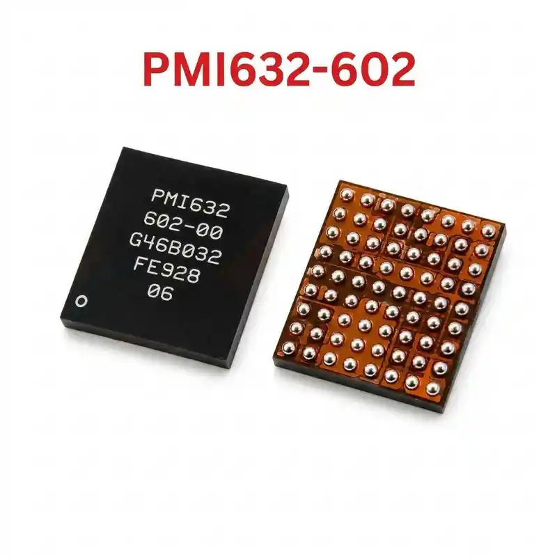
PMX55 IC
As low as
Rs 300.00
Worldwide shipping · Cash on Delivery
Product Details
====================================================================================================
QUALCOMM PMX55 / BBPMU (SNAPDRAGON X55 5G) IPHONE 12 SERIES REPAIR GUIDE
====================================================================================================
1. PRODUCT IDENTIFICATION & SILICON SPECIFICATIONS:
----------------------------------------------------------------------------------------------------
- Silicon Laser Marking: PMX55 [Line 2: 001-00 or PMX55-0]
- Commercial Hardware Name: Qualcomm PMX55 5G Baseband Power Management Subsystem
- Silicon Manufacturer: Qualcomm Technologies, Inc.
- Semiconductor Process Node: High-Density Advanced 5G Multi-Phase PMIC Process
- System Classification: Dedicated Cellular 5G Baseband Power Management Unit (BBPMU)
- Associated Modem Subsystem: Qualcomm Snapdragon X55 5G Modem (SDX55M - Sub-6GHz & mmWave)
- Companion RF Silicon: Qualcomm SDR865 (RF Transceiver) + Qualcomm QET5100 Envelope Tracker
- Package Form Factor: Fine-Pitch Wafer-Level Chip-Scale BGA (WLCSP BGA)
- Regulated Output Domains:
* Synchronous Multi-Phase Step-Down Buck Regulators:
- VDD_CORE_BB (SDX55M 5G Digital Core): 0.75V – 0.95V Dynamic Voltage Scaling.
- VDD_MODEM_MEM / VDD_DDR (Baseband LPDDR4X Memory Rails): Clean 1.10V / 1.80V.
- VDD_SDR_BUCK (RF Transceiver Buck Supplies): 1.05V – 1.30V.
* 15+ Ultra-Low Noise Linear (LDO) Regulators:
- PP1V8_SDRAM / VDD_EEPROM (1.80V Baseband Firmware Security IC).
- VDD_SDR_LDO (1.05V, 1.80V, 2.85V Clean Analog, PLL & LO Rails for SDR865).
- Dedicated clean rails for 5G RFFE front-end power amplifiers and Antenna Tuners.
* Clocks & System Handshake Lines:
- 38.4MHz / 19.2MHz reference clock buffer power delivery.
- Synchronous reset and handshake lines (BB_PMU_RST_N / BB_RST_N) via PCIe with Apple A14 Bionic.
2. COMPATIBLE SMARTPHONES (5G SUB-6 & MMWAVE):
----------------------------------------------------------------------------------------------------
- Apple iPhone 12 Series (All Models & Geographies):
* iPhone 12 Mini (Models A2176, A2398, A2400, A2399)
* iPhone 12 (Models A2172, A2402, A2404, A2403)
* iPhone 12 Pro (Models A2341, A2406, A2408, A2407)
* iPhone 12 Pro Max (Models A2342, A2410, A2412, A2411)
- Android 5G Flagships (Snapdragon 865 + X55 5G):
* Samsung Galaxy S20 / S20+ / S20 Ultra 5G (Snapdragon)
* Samsung Galaxy Note 20 / Note 20 Ultra 5G (Snapdragon)
* Xiaomi Mi 10 / Mi 10 Pro / Mi 10 Ultra
* OnePlus 8 / 8 Pro / 8T
3. TYPICAL BOARD-LEVEL FAULT SYMPTOMS:
----------------------------------------------------------------------------------------------------
- "No Service" / "Searching..." (Complete Baseband Inactivity):
* Status bar permanently shows "Searching..." or "No Service".
* Dialing *#06# fails to produce an IMEI popup; Settings > General > About displays blank "Modem Firmware".
* Root Cause: Defective PMX55 failing to output core/transceiver voltages, or broken interposer solder
joints between the logic board layers after a chassis drop.
- "Cellular Update Failed" System Alert:
* iOS pops up a system dialogue stating that cellular features are disabled until an update completes.
- VDD_MAIN or VDD_BOOST Short Circuit (Device Dead):
* Breakdown of internal high-side buck MOSFETs bridges the primary power line directly to ground
(0.000V in diode mode), causing DC power supply to trip overcurrent protection instantly.
- Extended Apple Logo Boot Hang (2 to 3 Minutes):
* Device remains hung on the Apple logo before booting or boot-looping due to timeout waiting for
the baseband handshake (BB_PMU_RST_N) during iOS kernel loading.
4. STEP-BY-STEP MULTIMETER TESTING & DIAGNOSTICS:
----------------------------------------------------------------------------------------------------
A. Cold Testing (Diode Mode Check - Board Powered Off, Battery Disconnected):
1. Set Multimeter to Diode Mode. Connect RED probe to PCB Ground (GND shield), probe with BLACK probe:
- VDD_MAIN Input Filtering Capacitors around PMX55: Normal ~360mV – 460mV.
- VDD_CORE_BB Buck Inductors: Normal ~80mV – 160mV (low impedance line, must NOT read 0.000V).
- SDR865 Transceiver Supply Lines: Normal ~250mV – 360mV.
- PP1V8_SDRAM / Baseband EEPROM Pin 8: Normal ~380mV – 480mV.
- Baseband Reset Test Points: Normal ~500mV – 650mV.
2. Short-Circuit Isolation:
- If a core rail or VDD_MAIN reads 0.000V, inject 0.85V (for core) or 3.8V (for VDD_MAIN)
limited to 1.5A. Inspect under thermal camera: if PMX55 illuminates bright white, lift the IC.
B. Live Operating Voltage Check (Hot Testing):
1. Connect DC bench power supply and trigger board power-on:
- Probe output coils situated adjacent to PMX55 (BBPMU):
* VDD_CORE_BB inductor must read 0.80V – 0.95V DC during network registration attempt.
* Transceiver coils must output stable 1.05V and 1.80V DC.
* Baseband EEPROM pin 8 must receive steady 1.80V DC.
- If rails pulse once (e.g., jump to 0.85V then drop to 0V), verify middle-layer interposer
continuity on the iPhone 12 sandwich board before condemning PMX55.
5. SOLDERING, REBALLING & REWORK SPECIFICATIONS:
----------------------------------------------------------------------------------------------------
- Double-Layer Sandwich Separation (iPhone 12 Specific):
* Place the iPhone 12 double-stacked logic board on a dedicated heating separation platform set to 185°C – 195°C.
* Separate the lower RF tier once interposer solder melts; PMX55 is located on the RF tier.
- Thermal Shielding & Surrounding Protection:
* PMX55 is situated near the Qualcomm SDX55M Baseband CPU and NAND storage chip.
* Always shield adjacent ICs using thick Kapton thermal tape and copper heat-sink coins.
- IC Removal:
* Apply high-grade, non-corrosive RMA BGA tacky flux around PMX55.
* Hot air rework parameters: 310°C – 325°C, airflow 35% – 40% with a medium precision nozzle.
* Heat evenly in circular motions for 35–45 seconds; lift chip vertically when all solder spheres melt.
- PCB Pad Cleanup:
* Add 183°C (Sn63/Pb37) leaded solder alloy to lower pad melting temperature.
* Smooth the pad matrix flat using fine copper solder wick braid with soldering iron set to 290°C – 300°C.
* Clean residue with 99% Isopropyl Alcohol (IPA); inspect pads under microscope for any lifted pads.
- Reballing Procedure:
* Use a dedicated 0.12mm middle-layer stencil compatible with iPhone 12 Qualcomm Baseband PMIC (PMX55).
* Apply 183°C leaded solder paste uniformly across all apertures.
* Reflow gently at 280°C with 20% airflow until uniform solder spheres emerge.
- Placement & Alignment:
* Spread a micro-thin layer of transparent tacky BGA flux over PCB pads.
* Align Pin 1 orientation dot on PMX55 with logic board silkscreen corner indicator.
* Reflow at 305°C – 315°C with 35% airflow; observe chip self-center on molten solder surface tension.
* Allow motherboard to cool naturally for 3–5 minutes before testing on DC power.
====================================================================================================
You may also like