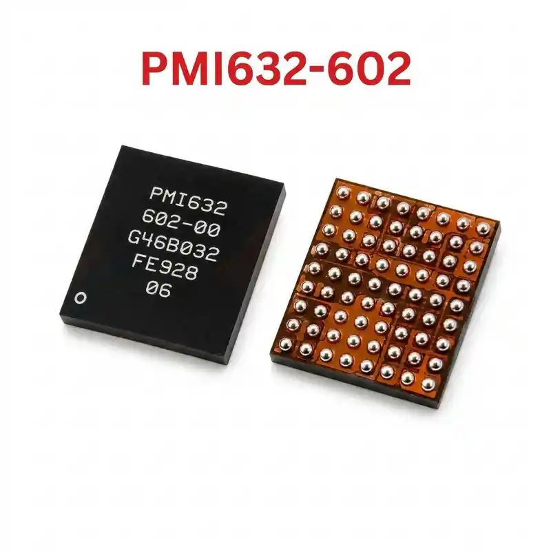
PMI8998 IC
As low as
Rs 180.00
Worldwide shipping · Cash on Delivery
Product Details
====================================================================================================
QUALCOMM PMI8998-003 FLAGSHIP SUB-PMIC / CHARGING & POWER IC REPAIR GUIDE
====================================================================================================
1. PRODUCT IDENTIFICATION & SILICON SPECIFICATIONS:
----------------------------------------------------------------------------------------------------
- Silicon Laser Marking: PMI8998 [Line 2: 003]
- Commercial Hardware Name: Qualcomm Flagship Intermediate Power Management Subsystem
- Silicon Manufacturer: Qualcomm Technologies, Inc.
- Semiconductor Process Node: High-Density Sub-Micron PMIC Process
- System Classification: Flagship Secondary Power Management IC (Charger / VPH_PWR / Type-C)
- Associated Main Platform: Qualcomm Snapdragon 835 (MSM8998 Octa-Core Platform)
- Companion Primary PMIC: Qualcomm PM8998 (002) + Qualcomm PM8005 (in select multi-phase boards)
- Package Form Factor: Fine-Pitch Wafer-Level Chip-Scale BGA (WLCSP BGA)
- Subsystem Blocks Inside PMI8998:
* Switching Fast Charger & USB-PD Controller:
- Supports Qualcomm Quick Charge 4.0 / 4+ and USB Type-C Power Delivery up to 27W.
* Primary System Bus Generator (VPH_PWR / VSYS):
- High-efficiency synchronous step-down buck converter producing 3.7V – 4.2V DC master rail.
* Type-C Port Controller & CC Detection:
- Dual CC line negotiation, plug orientation, role detection (DFP/UFP/DRP), and 5V OTG boost.
* Battery Management & Fuel Gauge:
- Precise ADC tracking battery state of charge, internal resistance, and NTC thermistor channels.
* Haptic Feedback Driver:
- High-bandwidth linear resonant actuator (LRA) haptic motor controller.
* Flash & Auxiliary Drivers:
- Dual-string high-current camera flash and torch LED drive circuit.
* SPMI Bus Interface:
- Inter-chip communication bus synchronized with Primary PM8998 and Snapdragon 835 AOSS.
2. COMPATIBLE FLAGSHIP SMARTPHONES (SNAPDRAGON 835 PLATFORM):
----------------------------------------------------------------------------------------------------
- Samsung Galaxy:
* Galaxy S8 (SM-G950U / SM-G9500 Snapdragon)
* Galaxy S8+ (SM-G955U / SM-G9550 Snapdragon)
* Galaxy Note 8 (SM-N950U / SM-N9500 Snapdragon)
- Google:
* Google Pixel 2 (Walleye) & Pixel 2 XL (Taimen)
- OnePlus:
* OnePlus 5 (A5000 - Cheeseburger) & OnePlus 5T (A5010 - Dumpling)
- Xiaomi:
* Xiaomi Mi 6 (Sagit) & Xiaomi Mi MIX 2 (Chiron)
- Sony Xperia:
* Xperia XZ Premium (G8141/G8142) & Xperia XZ1 / XZ1 Compact
- LG:
* LG V30 / V30+ (Snapdragon 835 models)
3. TYPICAL BOARD-LEVEL FAULT SYMPTOMS:
----------------------------------------------------------------------------------------------------
- Completely Dead Device (0.00A or 0.02A–0.03A Stuck Draw on DC Power Supply):
* Internal buck switching stage fails, preventing VPH_PWR generation. Main PM8998 and CPU get 0V.
- Type-C Fast Charging Failure / Extremely Slow Charging (Stuck at 0.40A – 0.50A):
* Phone fails to negotiate Quick Charge 4.0 or USB-PD protocols due to internal CC logic damage.
- Overheating Motherboard with Rapid Battery Drain (Self-Discharge):
* Internal short in the switching FET array causes PMI8998 to run scorching hot even in power-off state.
- VPH_PWR Direct Short to Ground (0.000V in Diode Mode):
* High-side buck MOSFET breakdown creates a zero-ohm bridge between battery power and ground.
- Hang on Boot Logo (Samsung Galaxy / Google / OnePlus Logo Freeze):
* Failure of the SPMI communication bus between PMI8998 and PM8998 halts the kernel during early boot.
4. STEP-BY-STEP MULTIMETER TESTING & DIAGNOSTICS:
----------------------------------------------------------------------------------------------------
A. Cold Testing (Diode Mode Check - Board Powered Off, Battery Disconnected):
1. Connect Multimeter RED probe to Motherboard Ground (GND shield), probe points with BLACK probe:
- VBUS Input Filter Capacitors (near Type-C port): Normal ~450mV – 560mV.
- Battery Connector Positive Terminal (VBAT): Normal ~400mV – 480mV.
- VPH_PWR Inductor (large switching coil next to PMI8998): Normal ~350mV – 450mV (0.000V = dead short).
- Type-C CC1 and CC2 Lines: Normal ~550mV – 650mV.
- SPMI Bus Clock & Data Lines: Normal ~400mV – 550mV.
- Boot Capacitor (BST): Check across capacitor terminals; must NOT read zero ohms (no short).
2. Short-Circuit Isolation:
- If VPH_PWR reads 0.000V, inject 3.8V DC (limited to 2.0A) onto the inductor.
Observe under thermal camera: if PMI8998 illuminates white-hot immediately, desolder the chip.
B. Live Operating Voltage Check (Hot Testing):
1. Insert USB Type-C charger into the phone:
- VBUS input capacitor: Must measure steady 5.0V, 9.0V, or 12.0V DC (depending on charger protocol).
- VPH_PWR Inductor: Must output steady 3.7V – 4.2V DC (even with battery disconnected).
- Battery terminal pins: Must measure pulsed 3.7V – 4.35V DC charging voltage.
2. Connect DC bench power supply and trigger power-on:
- VPH_PWR rail must remain rock solid at 3.8V–4.0V DC without fluctuating during CPU peak boot spike.
5. SOLDERING, REBALLING & REWORK SPECIFICATIONS:
----------------------------------------------------------------------------------------------------
- Thermal Protection & Surrounding Components:
* PMI8998 sits beneath a soldered RF shield in close proximity to the Snapdragon 835 CPU (PoP RAM)
and UFS storage chip.
* Always shield neighboring CPU and UFS memory with thick Kapton tape and copper cooling coins.
- IC Removal:
* Dispense high-grade non-corrosive RMA BGA tacky flux around PMI8998.
* Hot air rework station settings: 320°C – 335°C, airflow 35% – 45% (medium precision nozzle).
* Circle nozzle uniformly for 30–40 seconds. Once all solder joints liquefy, lift chip vertically.
- PCB Pad Cleanup:
* Apply 183°C (Sn63/Pb37) leaded solder to logic board footprint to dilute high-melt factory unleaded alloy.
* Flatten pad matrix using copper desoldering braid with soldering iron set to 290°C – 300°C.
* Clean thoroughly with 99% Isopropyl Alcohol (IPA); inspect pads under microscope for any lifted pads.
- Reballing Procedure:
* Use a dedicated or universal 0.12mm BGA stencil matching the PMI8998 footprint.
* Spread 183°C leaded solder paste smoothly across all apertures with a flexible scraper.
* Reflow gently at 280°C with 20% airflow until uniform solder spheres form.
- Placement & Alignment:
* Spread a thin, transparent layer of tacky BGA flux onto PCB pads.
* Align Pin 1 dot on the PMI8998 chip with silkscreen corner indicator.
* Reflow at 310°C – 320°C with 35% airflow; observe the chip pull into place by solder surface tension.
* Allow motherboard to cool naturally for 3–5 minutes before connecting DC power or battery.
====================================================================================================
You may also like