
M-061 (Tin Dragging Needle Set
As low as
Rs 0.00
Worldwide shipping · Cash on Delivery
Product Details
================================================================================
MAANT M061 PRECISION TIN DRAGGING & FPC REBUILDING TECHNICAL GUIDE
================================================================================
1. THERMODYNAMICS & SURFACE TENSION WETTING PRINCIPLES:
- Mechanics of the Gold-Plated Spherical Ball Tip:
* Standard soldering iron chisel/knife tips feature sharp corners that scratch delicate solder mask and apply concentrated shear forces, which rip micro-lands off flexible printed circuits (FPCs).
* The MaAnt M061 utilizes a pure copper sphere plated with 24K gold. Pure copper provides instantaneous thermal conduction, while the gold flash layer prevents copper oxidation and promotes rapid solder wetting without forming stubborn copper-oxide dross.
* The spherical profile relies on the Young-Laplace capillary wetting equation: molten solder naturally clings to the curved golden meniscus of the ball. When rolled across an array of fluxed copper landing pads, surface tension transfers an identical volume of solder to each pad, forming uniform, rounded micro-domes.
- Thermal Shielding for Plastic FPC Housings:
* High-density smartphone FPC connectors (screen, battery, camera, and charge port B2B sockets) are molded from liquid-crystal polymer (LCP) with melting thresholds around 260°C – 280°C.
* Direct contact with a 340°C soldering iron tip immediately scorches and melts the internal plastic guide walls.
* The M061 dragging needle isolates heat transfer: when preheated under controlled 240°C hot air or lightly touched by an iron tip at its shank, the spherical tip rolls across the metal connector pins, depositing solder exclusively on the copper terminals without touching the plastic dividers.
--------------------------------------------------------------------------------
2. COMPATIBLE SOLDERING ALLOYS & FLUX COMPOSITION:
- Solder Alloy Selection:
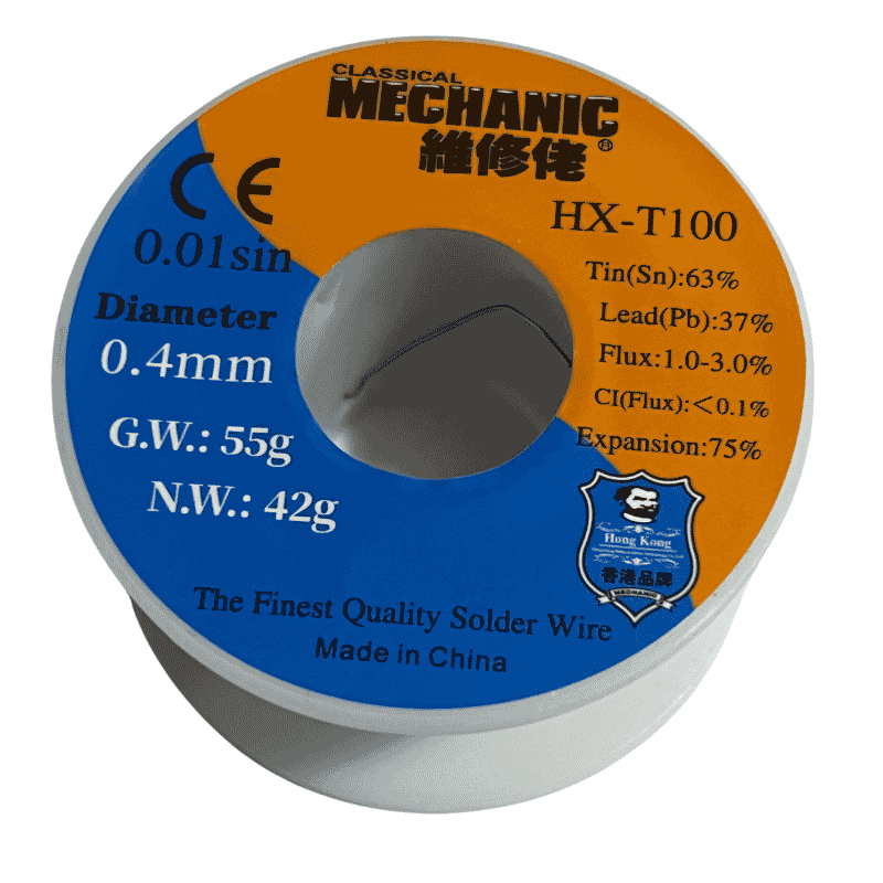
* FPC Connector Pin Replacements: Sn63/Pb37 leaded paste (Melting point: 183°C) or specialized low-temperature Sn42/Bi58 (Melting point: 138°C) where adjacent temperature-sensitive components cannot tolerate heat.
* BGA Substrate Land Leveling: Standard Sn63/Pb37 leaded alloy is strictly recommended to ensure high mechanical shear resistance and prevent intermetallic voiding during final IC installation.
- Flux Selection:
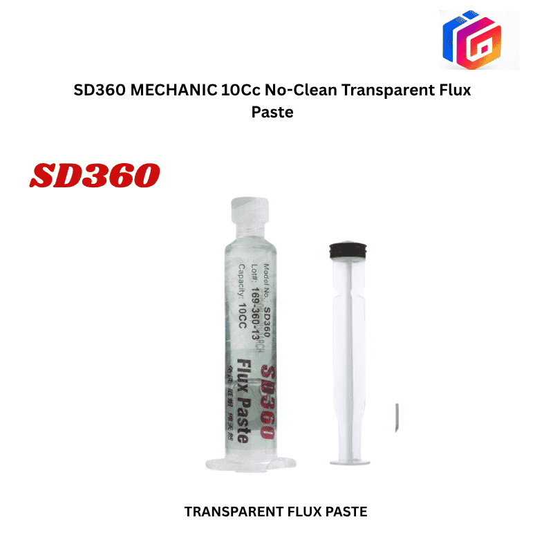
* Highly active no-clean synthetic tacky flux (Amtech NC-559-ASM or Kingbo RMA-218). High boiling-point flux vehicles ensure smooth liquid meniscus glide and prevent solder spatter.
--------------------------------------------------------------------------------
3. STEP-BY-STEP WORKFLOW FOR FPC CONNECTOR PIN RE-TINNING & BGA SPREADING:
STEP 1: Tool Assembly & Collet Tensioning
- Unscrew the knurled golden aluminum collet chuck on the MaAnt M061 carbon fiber handle.
- Insert the cylindrical shank of the gold-plated spherical needle into the four-jaw micro-chuck.
- Hand-tighten the chuck firmly to ensure zero axial wobble or lateral flex during micro-manipulation under the microscope.
STEP 2: Motherboard / FPC Site Preparation
- Place the logic board or flexible cable into a weighted motherboard fixture.
- Inspect the target FPC connector or pad array under 20x – 40x magnification.
- Apply a micro-bead of tacky flux across the entire row of connector pins using an ultra-fine applicator.
- If pins are oxidized or blackened, clean lightly with a fiberglass micro-pen soaked in 99.9% anhydrous IPA before applying flux.
STEP 3: Tin Loading & Meniscus Formation
- Method A (Direct Iron Touch):
* Touch a clean soldering iron tip (set to 320°C with Sn63/Pb37 alloy) lightly against the upper shank of the M061 needle while holding the ball near the repair site. Solder will flow down the golden shank and coat the spherical ball into a molten droplet.
- Method B (Hot-Air Aided Roll):
* Apply a minute smear of Sn63/Pb37 solder paste across the pins.
* Set hot air station to 240°C (Airflow: 25%) directed at the pins.
* As the paste transitions to liquidus, advance the M061 ball tip into the molten pool.
STEP 4: Micro-Drag Solder Planarization
- Hold the ultralight carbon fiber handle at a 45° angle, resting the hand on an anti-vibration wrist block.
- Lightly glide the spherical ball tip horizontally across the pin row in a single, continuous, sweeping motion.
- Molten solder will bridge momentarily behind the moving sphere and snap cleanly onto each individual pin due to the higher surface energy of the fluxed pin lands.
- The spherical geometry guarantees zero mechanical contact with adjacent plastic partitions, preventing melted connector walls.
STEP 5: Cleaning & Microscopic Inspection
- Allow the solder joints to solidify for 5 seconds.
- Flush the connector cavity with 99.9% anhydrous IPA using a soft-bristle micro-brush to dissolve all flux residues.
- Inspect under 30x magnification:
* Confirm every pin possesses an identical, bright, convex solder meniscus.
* Verify zero solder bridging between adjacent pins (0.35 mm pitch).
* Verify zero heat deformation or warping on the plastic FPC guide ridges.
--------------------------------------------------------------------------------
4. TECHNICIAN RISK MITIGATION & PROCESS CONTROL MATRIX:
┌────────────────────────────────┬────────────────────────────────┬────────────────────────────────────────────────────┐
│ Process Error / Fault │ Resulting Defect │ Corrective Action & Best Practice │
├────────────────────────────────┼────────────────────────────────┼────────────────────────────────────────────────────┤
│ Solder bridges between fine- │ Direct short circuit between │ Apply fresh tacky flux and re-drag the clean M061 │
│ pitch FPC pins (0.35mm pitch) │ adjacent signal/power rails │ tip across pins without adding extra solder. │
├────────────────────────────────┼────────────────────────────────┼────────────────────────────────────────────────────┤
│ Gold plating stripped off tip │ Bare copper oxidizes rapidly; │ Do not file or scrape the ball tip with abrasives; │
│ (Tip blackened and repels tin) │ solder refuses to wet the tip │ replace with a fresh M061 tip from the capsule. │
├────────────────────────────────┼────────────────────────────────┼────────────────────────────────────────────────────┤
│ Excessive downward hand │ Collapses FPC spring contacts; │ Rest hand on bench; use feather-light contact; let │
│ pressure during drag motion │ bends connector metal pins │ liquid surface tension do the wetting work. │
├────────────────────────────────┼────────────────────────────────┼────────────────────────────────────────────────────┤
│ Insufficient flux during drag │ Cold solder peaks, icicles, │ Always flood pins with high-grade tacky rosin flux │
│ motion across BGA pads │ and micro-solder balls │ before dragging to ensure clean surface release. │
├────────────────────────────────┼────────────────────────────────┼────────────────────────────────────────────────────┤
│ Hot air temperature > 270°C │ Melts LCP plastic connector │ Keep hot air strictly at 230°C–245°C when working │
│ directed directly at FPC body │ housing and warps lock clips │ near plastic connectors; use focused micro-nozzle. │
└────────────────────────────────┴────────────────────────────────┴────────────────────────────────────────────────────┘
================================================================================
You may also like