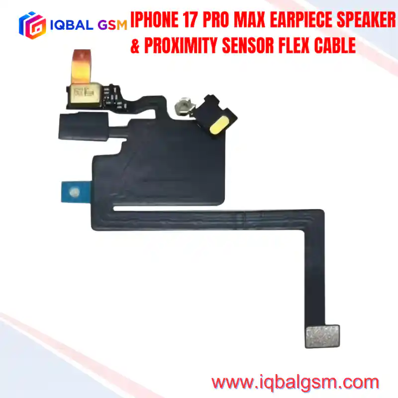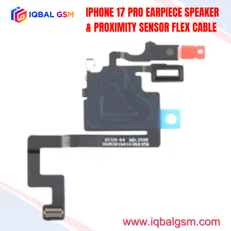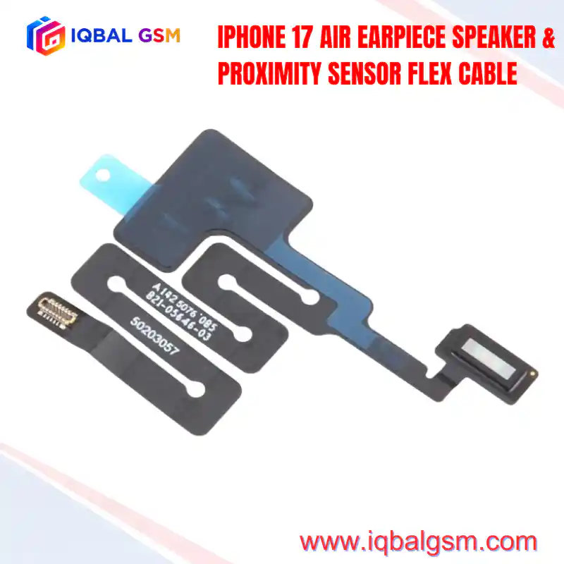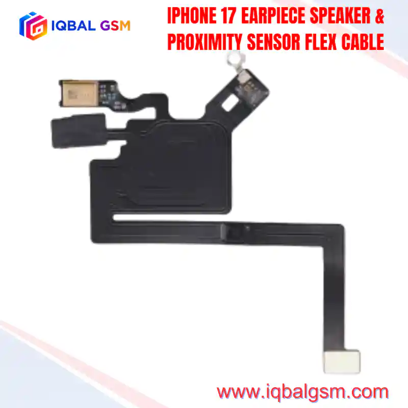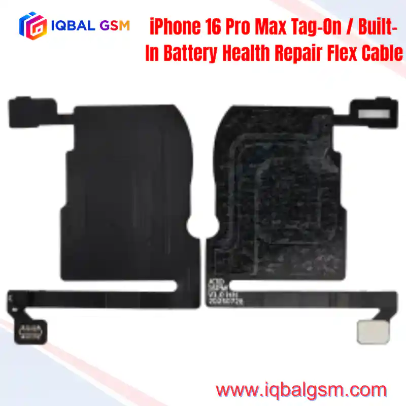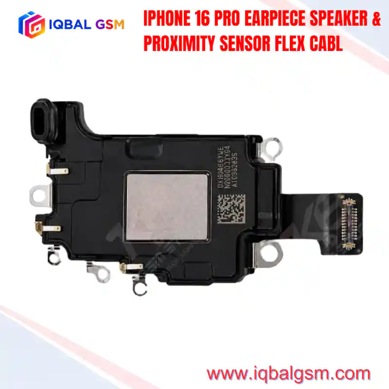

IPHONE 15 PLUS EARPIECE SPEAKER & PROXIMITY SENSOR FLEX CABLE
As low as
Rs 1000.00
Worldwide shipping · Cash on Delivery
Product Details
====================================================================================================
IPHONE 15 PLUS EARPIECE SPEAKER & PROXIMITY SENSOR FLEX CABLE TECHNICAL REPAIR MANUAL
====================================================================================================
1. ARCHITECTURAL OVERVIEW & 6.7-INCH DYNAMIC ISLAND IMPLEMENTATION
----------------------------------------------------------------------------------------------------
The iPhone 15 Plus brings the Dynamic Island pill-and-hole cutout to the 6.7-inch non-Pro form factor.
This design incorporates a decoupled acoustic and optical configuration:
* Decoupled Speaker Driver: The acoustic ear speaker driver is seated in the upper top edge of the
anodized aluminum frame rather than on the display assembly.
* Flex Assembly Mounting: The 15Plus FPC assembly mounts directly to the rear of the 6.7-inch Super
Retina XDR display panel immediately below the Dynamic Island aperture.
* Mechanical Contact Pads: Features spring-loaded, gold-plated beryllium-copper leaf contacts that
interface with the chassis-housed ear speaker when the display is seated and screwed into place.
* Optical Array: Positions the VCSEL infrared emitter, receiving photodiode, and RGB multi-spectral
ambient light sensor directly beneath the OLED display's transparent sensor window.
* Microphone Array: Integrates an acoustic dampening boot surrounding the top directional microphone,
handling phone call background noise cancellation, Siri audio capture, and front camera video audio.
2. LOGIC BOARD POWER RAILS, SIGNALS & BUS TOPOLOGY
----------------------------------------------------------------------------------------------------
The iPhone 15 Plus sensor flex interfaces with the A16 Bionic Application Processor and system PMIC
across high-speed digital buses and dedicated power lines:
* PP3V0_PROX_ALS: Filtered 3.0V supply rail delivering operating voltage to the infrared proximity
emitter and ambient light sensor package.
* PP1V8_S2 / PP1V8_IO: 1.8V digital logic supply powering internal registers, control circuitry, and
I2C pull-up terminations.
* I2C_SDA / I2C_SCL (I2C Sensor Bus): 400 kHz bidirectional serial bus reporting ambient light lux,
correlated color temperature (CCT), and proximity state transitions to the SoC.
* SPK_EAR_POS / SPK_EAR_NEG: Differential amplified speaker audio rail (8 Ohm nominal impedance)
delivering audio from the primary audio codec through the leaf-spring terminals.
* CRYPTOGRAPHIC HARDWARE BINDING: The ambient light sensor contains an integrated factory-programmed
EEPROM cryptographically tied to the Secure Enclave Processor (SEP). Replacing this flex without
IC transfer or programmer cloning results in True Tone lockout and auto-brightness failure.
3. FAILURE MODES & SYSTEM-LEVEL SYMPTOMS
----------------------------------------------------------------------------------------------------
* 180-Second Watchdog Kernel Panic (PRST / I2C Sensor Failure):
Liquid intrusion through the upper speaker mesh often leads to dendrite formation or corrosion
between the PP3V0 supply and I2C data/clock lines. When the SoC watchdog timer fails to poll sensor
registers, the phone reboots every 180 seconds with panic logs indicating `Thermal/Sensor Watchdog Timeout`.
* True Tone Disabled & Auto-Brightness Lockout:
Installing an unprogrammed replacement flex strips True Tone from Settings -> Display & Brightness,
and locks display luminance to a fixed baseline value.
* Proximity Detection Failure During Calls:
The screen fails to sleep during active voice calls or remains blacked out after removing the phone
from the ear. Typically caused by silicone light-pipe misalignment or dust accumulation over the
Dynamic Island sensor window.
* Muffled or Distorted Ear Speaker Audio:
Misalignment or oxidation of the gold leaf spring contacts preventing proper electrical contact
with the chassis ear speaker terminals.
4. STEP-BY-STEP REPAIR, SOLDERING & TRANSPLANT WORKFLOW
----------------------------------------------------------------------------------------------------
To retain full native Face ID, True Tone, and factory calibration without software mismatch errors,
technicians must transplant the original ambient light sensor onto a compatible replacement receiver
FPC (e.g., JCID / i2C / QianLi):
A. DISASSEMBLY & EXTRACTION:
1. Place the screen assembly on a heating pad at 70°C–75°C for 2 minutes to soften the factory adhesive.
2. Apply 99.9% isopropyl alcohol around the plastic bracket holding the sensor cluster.
3. Using ultra-fine curved ESD tweezers, lift the flex assembly away from the display bracket.
CAUTION: Never pry directly against the optical glass surface of the ALS IC; mechanical stress will
delaminate the photodiode die from its ceramic substrate.
B. SENSOR CHIP TRANSPLANTATION & MICRO-SOLDERING:
1. Secure the original damaged flex under a stereo microscope in a dedicated micro-soldering fixture.
2. Apply high-grade tacky flux (Amtech NC-559-V2) across the ALS sensor pins.
3. Adjust the hot air rework station to 280°C–300°C with 30% airflow using a fine 3.5mm nozzle.
4. Heat uniformly around the chip perimeter until the solder reflows, then lift the IC with vacuum tweezers.
5. Remove residual lead-free solder from the chip pads using 0.6mm desoldering wick and low-melt solder wire.
6. Reball using a dedicated 0.12mm BGA stencil and 183°C tin-lead/tin-bismuth solder paste.
7. Align and reflow the reballed sensor onto the replacement receiver flex cable.
C. EEPROM BACKUP & PROGRAMMING (WHEN USING RECOVERY FPCS):
1. Connect the original flex to a hardware programmer (JCID V1SE / V1S Pro or i2C 2CS).
2. Read and verify the stored ALS factory calibration data payload.
3. Connect the new tag-on receiver flex to the programmer board.
4. Write the original data payload to the replacement FPC and verify checksum integrity.
5. POST-ASSEMBLY DIAGNOSTICS & SYSTEM VALIDATION
----------------------------------------------------------------------------------------------------
* Mechanical Leaf-Spring Inspection: Verify contact prongs are raised at least 0.4mm above the plastic
bracket to guarantee positive contact pressure against the chassis speaker terminals.
* True Tone & Auto-Brightness: Power on the device, verify True Tone toggle is active in Control Center,
and confirm dynamic brightness adjustment under varying light conditions.
* Proximity Sensor Verification: Place a test phone call and confirm the screen immediately blanks
when an object approaches within 20mm of the Dynamic Island cutout.
* Stability Audit: Monitor device operation for a minimum of 15 minutes to verify zero unexpected reboots
or watchdog panic entries in iOS Analytics logs.
====================================================================================================
You may also like