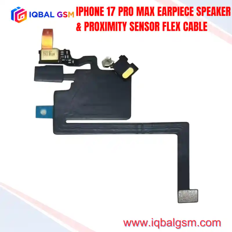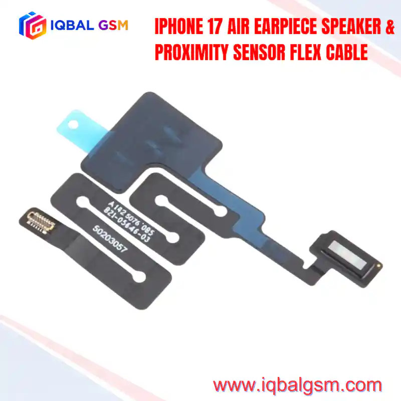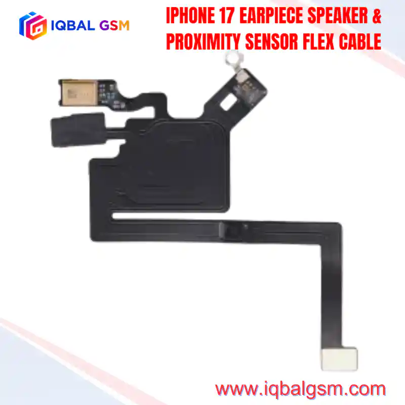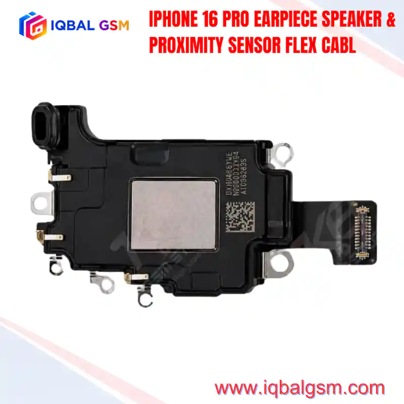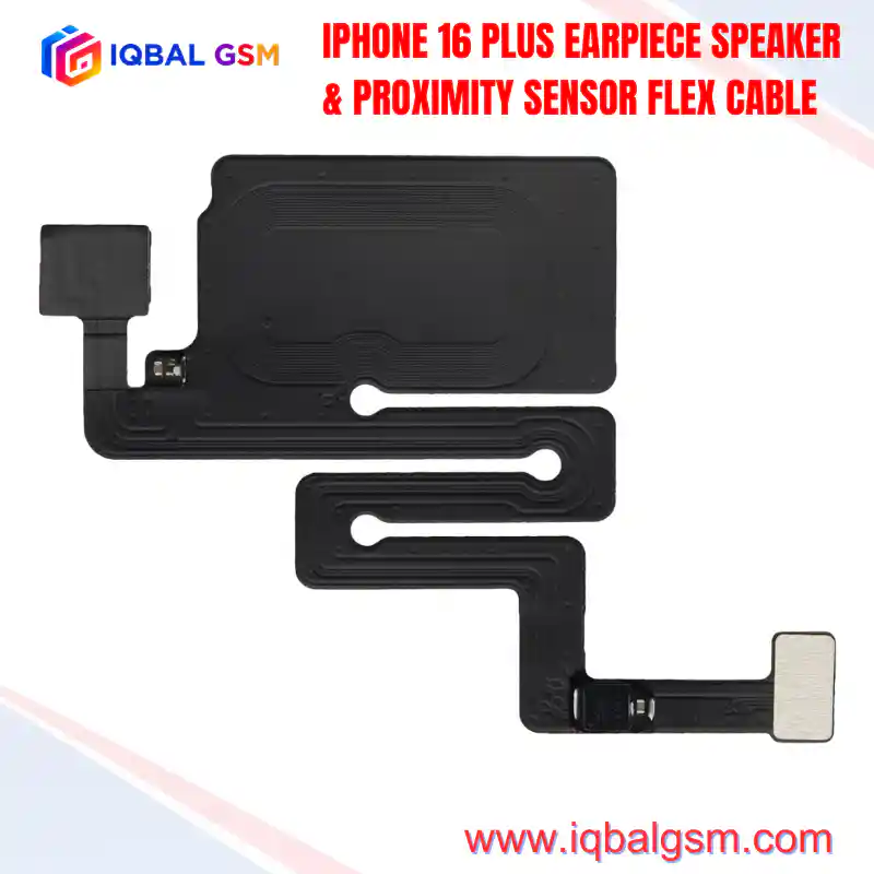

IPHONE 17 PRO EARPIECE SPEAKER & PROXIMITY SENSOR FLEX CABLE
As low as
Rs 0.00
Worldwide shipping · Cash on Delivery
Product Details
====================================================================================================
IPHONE 17 PRO EARPIECE SPEAKER & PROXIMITY SENSOR FLEX CABLE TECHNICAL REPAIR MANUAL
====================================================================================================
1. ARCHITECTURAL OVERVIEW & PRO PLATFORM INTEGRATION
----------------------------------------------------------------------------------------------------
The iPhone 17 Pro incorporates a 6.3-inch Super Retina XDR 120Hz ProMotion display with ultra-thin
border encapsulation and a Grade-5 Titanium frame. The acoustic and optical management utilizes Apple's
decoupled subsystem architecture:
* Upper Chassis Acoustic Enclosure: The ear speaker transducer is recessed into a CNC-machined cavity
in the top perimeter of the titanium frame rather than adhered to the display glass.
* Flex Assembly Mounting: The 17Pro FPC flex assembly mounts to an alignment bracket affixed to the rear
of the 6.3-inch OLED panel beneath the Dynamic Island cutout.
* Spring-Loaded Contact Interface: Connects to the chassis ear speaker via gold-plated beryllium-copper
leaf springs that mate with terminal lugs under mechanical compression when the display is sealed.
* Multi-Spectrum Optical Cluster: Aligns the miniaturized VCSEL infrared proximity emitter, photodiode
receiver, and high-precision multi-spectral ambient light sensor (ALS) with the transparent display window.
* Noise-Canceling Acoustic Microphone: Houses an integrated forward-facing microphone sealed within an
acoustic silicone boot, providing reference sound dampening for phone calls, spatial audio capture, and Siri.
2. LOGIC BOARD POWER RAILS, SIGNALS & BUS TOPOLOGY
----------------------------------------------------------------------------------------------------
The iPhone 17 Pro sensor flex routes power, control, and acoustic signals between the application processor,
the PMIC, and the audio subsystem:
* PP3V0_PROX_ALS: Filtered 3.0V supply rail delivering operating bias to the infrared proximity emitter
and the ambient light sensor module.
* PP1V8_S2 / PP1V8_IO: 1.8V digital logic supply powering internal sensor registers, logic gates, and
I2C pull-up terminations.
* I2C_SDA / I2C_SCL (I2C Sensor Bus): 400 kHz bidirectional serial bus reporting ambient lux,
correlated color temperature (CCT), and proximity threshold transitions to the application processor.
* SPK_EAR_POS / SPK_EAR_NEG: Differential amplified speaker audio drive lines (8 Ohm nominal impedance)
routed from the audio amplifier to the spring contact terminals.
* SECURE ENCLAVE HARDWARE PAIRING: The ambient light sensor incorporates factory-burned EEPROM calibration
registers cryptographically bound to the Secure Enclave Processor (SEP). Replacing this flex without
sensor transplantation or cloning results in loss of True Tone and disables dynamic auto-brightness.
3. FAILURE MODES & SYSTEM-LEVEL SYMPTOMS
----------------------------------------------------------------------------------------------------
* 180-Second Watchdog Kernel Panic (PRST / I2C Sensor Failure):
Moisture intrusion through the top speaker mesh often creates dendritic corrosion between the 3.0V
supply rail and adjacent I2C clock/data lines. When the SoC kernel fails to poll the sensor registers,
the device reboots every 180 seconds, logging `Thermal/Sensor Watchdog Timeout`.
* True Tone Disabled & Auto-Brightness Lockout:
Installing an unprogrammed aftermarket flex strips the True Tone option from iOS Settings -> Display
& Brightness, locking the display to static default luminance.
* Proximity Failure During Active Calls:
The display fails to turn off when brought near the ear during calls, or remains blacked out after
the call ends. Commonly caused by silicone prism displacement or optical window obstruction beneath
the Dynamic Island cutout.
* Earpiece Audio Attenuation / Distortion:
Oxidation or mechanical collapse of the gold leaf spring contacts preventing proper ohmic contact
with the chassis ear speaker terminals.
4. STEP-BY-STEP REPAIR, SOLDERING & TRANSPLANT WORKFLOW
----------------------------------------------------------------------------------------------------
To retain native True Tone, auto-brightness, and Face ID calibration without software warnings, technicians
must transplant the original ambient light sensor onto a compatible replacement receiver FPC
(e.g., JCID / i2C / QianLi):
A. DISASSEMBLY & EXTRACTION:
1. Place the screen assembly on a heating pad at 70°C–75°C for 2 minutes to soften the factory adhesive.
2. Apply 99.9% isopropyl alcohol around the plastic bracket holding the sensor cluster.
3. Using ultra-fine curved ESD tweezers, lift the flex assembly away from the display bracket.
CAUTION: Never pry directly against the optical glass surface of the ALS IC; mechanical stress will
delaminate the photodiode die from its ceramic substrate.
B. SENSOR CHIP TRANSPLANTATION & MICRO-SOLDERING:
1. Secure the original damaged flex under a stereo microscope in a dedicated micro-soldering fixture.
2. Apply high-grade tacky flux (Amtech NC-559-V2) across the ALS sensor pins.
3. Adjust the hot air rework station to 280°C–300°C with 30% airflow using a fine 3.5mm nozzle.
4. Heat uniformly around the chip perimeter until the solder reflows, then lift the IC with vacuum tweezers.
5. Remove residual lead-free solder from the chip pads using 0.6mm desoldering wick and low-melt solder wire.
6. Reball using a dedicated 0.12mm BGA stencil and 183°C tin-lead/tin-bismuth solder paste.
7. Align and reflow the reballed sensor onto the replacement receiver flex cable.
C. EEPROM BACKUP & PROGRAMMING (WHEN USING RECOVERY FPCS):
1. Connect the original flex to a hardware programmer (JCID V1SE / V1S Pro or i2C 2CS).
2. Read and verify the stored ALS factory calibration data payload.
3. Connect the new tag-on receiver flex to the programmer board.
4. Write the original data payload to the replacement FPC and verify checksum integrity.
5. POST-ASSEMBLY DIAGNOSTICS & SYSTEM VALIDATION
----------------------------------------------------------------------------------------------------
* Spring-Loaded Contact Inspection: Verify leaf-spring prongs extend at least 0.4mm above the plastic
bracket to guarantee positive contact pressure against the chassis speaker terminals.
* True Tone & Auto-Brightness: Power on the device, verify True Tone toggle is active in Control Center,
and confirm dynamic brightness adjustment under varying light conditions.
* Proximity Detection Test: Place a test phone call and confirm the OLED screen immediately blanks
when an opaque object approaches within 20mm of the Dynamic Island cutout.
* System Stability Verification: Monitor device operation for a minimum of 15 minutes to verify zero
unexpected reboots or watchdog panic entries in iOS Analytics logs.
====================================================================================================
You may also like