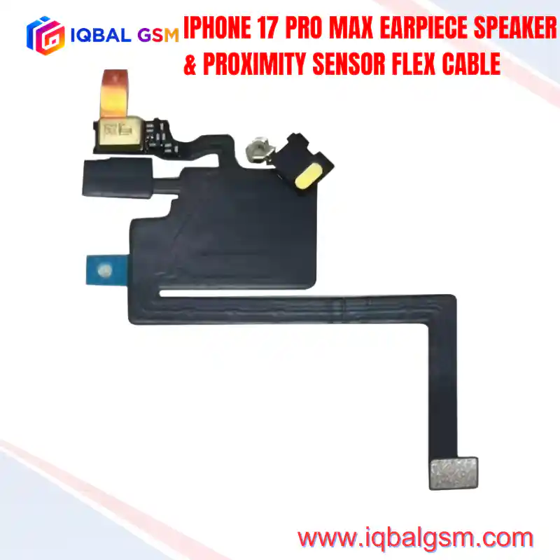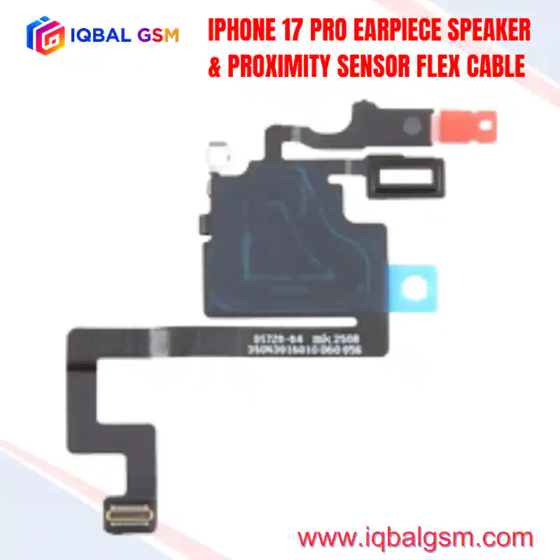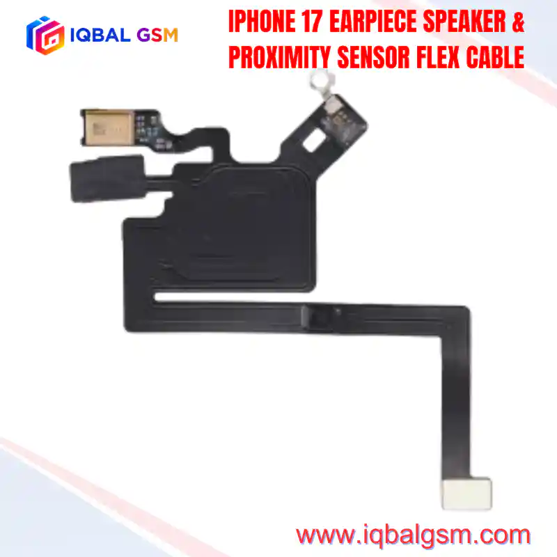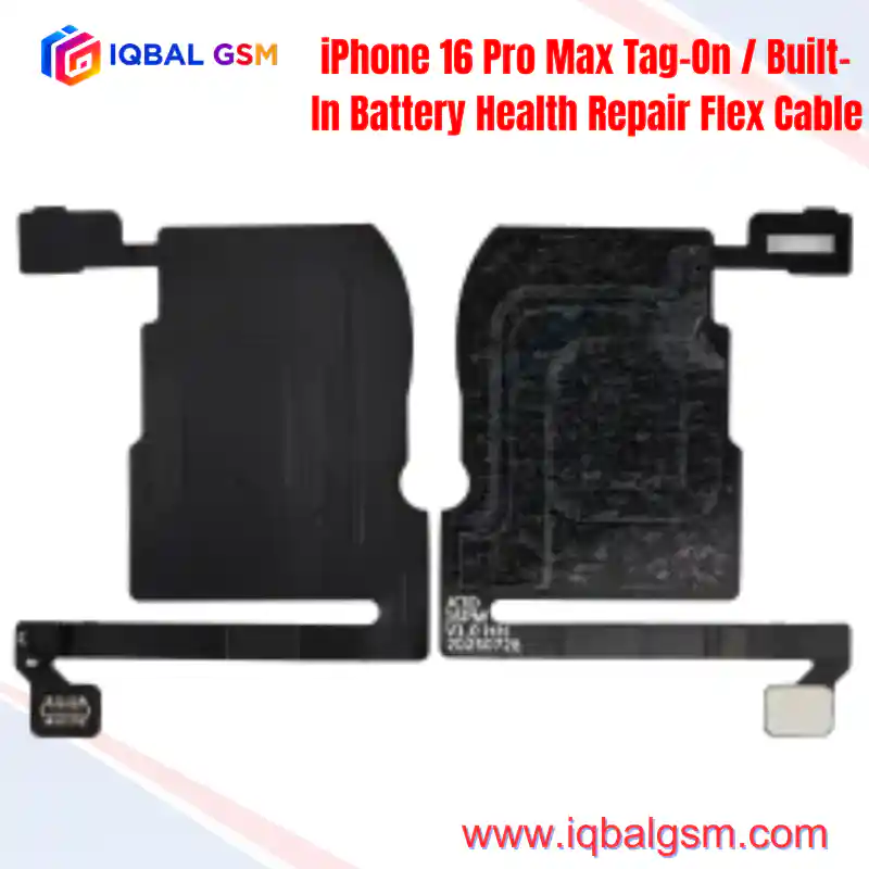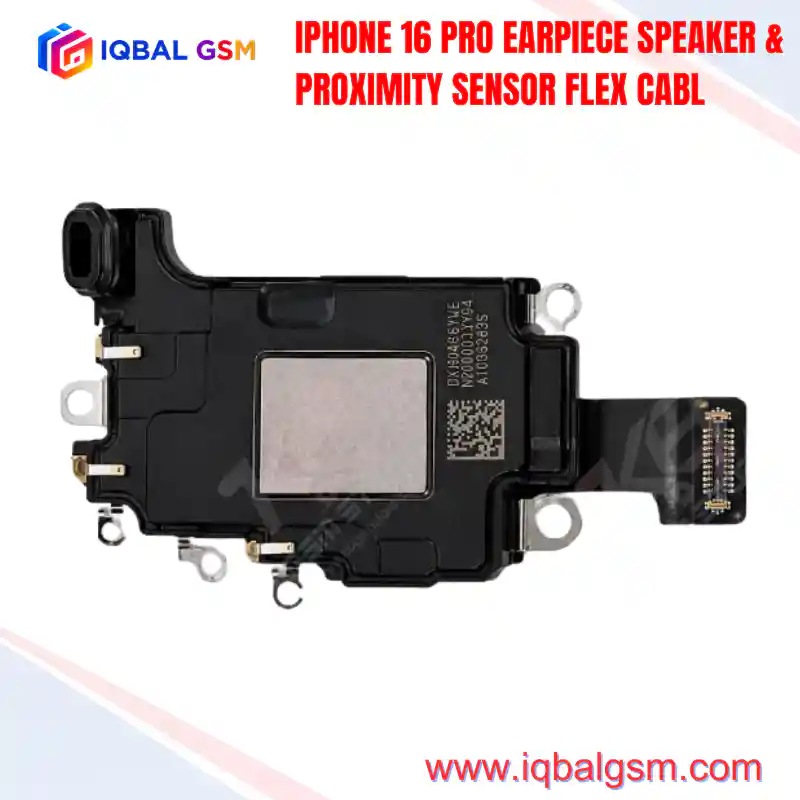

IPHONE 13 PRO EARPIECE PROXIMITY SENSOR FLEX CABLE
As low as
Rs 0.00
Worldwide shipping · Cash on Delivery
Product Details
================================================================================
IPHONE 13 PRO EARPIECE PROXIMITY SENSOR FLEX REWORK & CALIBRATION GUIDE
================================================================================
1. SILICON SENSOR TELEMETRY & AMBIENT LIGHT SENSOR (ALS) PAIRING:
In the iPhone 13 Pro, the earpiece proximity flex is tied directly to system security, display colorimetry, and thermal shutdown loops:
A. Cryptographic Sensor Bus & True Tone Lock:
- The Ambient Light Sensor (ALS) on the iPhone 13 Pro flex is paired via an encrypted digital handshake to the A15 Bionic Application Processor and the display serial registry.
- If the flex cable is torn during screen separation and replaced with an unprogrammed aftermarket part:
1. True Tone is permanently disabled in iOS Control Center.
2. Auto-Brightness sliders become unresponsive.
3. Face ID may fail to complete facial enrollment or fail depth tracking because the flood illuminator calibration data is linked through the shared ALS bus.
B. The I2C Bus Fault & 3-Minute Bootloop Panic:
- The proximity sensor and ambient light sensor communicate across the `I2C2` / `I2C3` serial bus (1.8V pull-up logic).
- When liquid ingress occurs at the top earpiece speaker grill, corrosion bridges the 3.0V supply rail to the I2C SDA/SCL lines.
- The kernel watchdog detects an unacknowledged sensor polling response (`panic-full: watchdogd: i2c2 bus stuck low, thermal/sensor failure`), forcing a hard reboot after exactly 180 seconds.
--------------------------------------------------------------------------------
2. STEP-BY-STEP REWORK PROCEDURE: SENSOR TRANSPLANT & JCID / LUBAN PROGRAMMING:
STEP 1: Safe Display Screen Notch Extraction
- Heat the top notch area of the iPhone 13 Pro display assembly on a heating mat at 70°C for 2 minutes to soften the factory adhesive securing the optical sensor prisms.
- Apply a micro-droplet of 99.9% anhydrous IPA under the proximity sensor guide bracket.
- Using an ultra-thin curved pry blade (e.g., QianLi 007 or 2UUL blade), gently slide beneath the microphone and ambient light sensor window.
- Lift the flex vertically out of the plastic display bezel bracket. NEVER pull by the ribbon tail; the internal copper traces will snap.
STEP 2: Sensor Component Micro-Transplant (Preserving Original ALS)
- If the original flex ribbon is torn but the sensors are intact:
* Secure the damaged iPhone 13 Pro flex under the stereomicroscope in a magnetic holding fixture.
* Apply NC-559-ASM tacky rosin flux over the underside solder joints of the original ALS/proximity sensor die.
* Set hot air station to 280°C – 300°C (Airflow: 20%) with a micro-nozzle.
* Heat from the underside of the flex for 12 seconds until the lead-free solder liquifies, then lift the bare sensor die using precision titanium tweezers.
* Reball the sensor using 183°C Sn63/Pb37 solder paste and transfer onto the new replacement iPhone 13 Pro blank flex cable.
STEP 3: Programmer Read / Write (Tag-On / Non-Removal Method via JCID V1SE / LuBan L3)
- If the original sensor is destroyed and a new flex must be calibrated:
* Connect the replacement iPhone 13 Pro earpiece flex to the "Receiver / FPC Ear Speaker" board on the JCID V1SE / V1S Pro or LuBan L3.
* Click "Detect / Read".
* Connect the phone via USB cable and click "Cloud Read & Repair True Tone / Face ID".
* Burn the original factory calibration data from the phone's NAND cloud record into the new flex MCU.
* Confirm "Write Complete" status on the programmer LCD screen.
STEP 4: Installation & Acoustic Sealing
- Apply fresh OEM pre-cut double-sided adhesive tape into the top notch cavity of the display.
- Carefully press the optical proximity window and ambient light sensor into their alignment registration pins.
- Ensure the microphone rubber acoustic gasket is seated flush to avoid muffled Siri / speakerphone audio.
- Connect the flex B2B connector to the top of the iPhone 13 Pro logic board and reinstall the metal retaining shield.
--------------------------------------------------------------------------------
3. FAULT DETECTION MATRIX & BOARD-LEVEL TELEMETRY VERIFICATION:
┌────────────────────────────────┬────────────────────────────────┬────────────────────────────────────────────────────┐
│ Observed Defect / Error │ Underlying Hardware Failure │ Corrective Action & Verification │
├────────────────────────────────┼────────────────────────────────┼────────────────────────────────────────────────────┤
│ Screen remains ON during calls;│ Proximity IR emitter open; │ Check diode reading on Pin 5 (ALS_INT); replace │
│ accidental cheek touches │ misaligned plastic light prism │ optical sensor or realign bracket into notch. │
├────────────────────────────────┼────────────────────────────────┼────────────────────────────────────────────────────┤
│ Phone reboots every 3 minutes │ I2C2 data line shorted to │ Inspect flex under microscope for green corrosion; │
│ (Kernel Panic: i2c2 timeout) │ ground via liquid corrosion │ clean with IPA or replace corrupted flex cable. │
├────────────────────────────────┼────────────────────────────────┼────────────────────────────────────────────────────┤
│ True Tone option missing in │ Aftermarket flex installed │ Read data via JCID V1SE/LuBan from phone NAND and │
│ iOS Display & Brightness │ without migrating ALS data │ write to flex, or transplant original ALS chip. │
├────────────────────────────────┼────────────────────────────────┼────────────────────────────────────────────────────┤
│ Ear speaker sound low, │ Corroded audio contact pads; │ Clean gold landing pads with fiberglass pen; check │
│ distorted, or completely silent│ damaged chassis speaker coil │ earpiece speaker coil resistance (nominal ~6-8 Ω). │
├────────────────────────────────┼────────────────────────────────┼────────────────────────────────────────────────────┤
│ Siri cannot hear user on front │ Front top noise-cancelling │ Inspect microphone port mesh for adhesive blockage;│
│ mic; FaceTime voice muffled │ microphone damaged during prying│ replace mic unit or clear acoustic channel. │
└────────────────────────────────┴────────────────────────────────┴────────────────────────────────────────────────────┘
B. Cold Diode-Mode Ground Reference Values (Red Probe on GND, Black on Connector Pin):
- Pin 1 [PP3V0_ALS_VDD] (3.0V Optical Sensor Supply): 0.520V – 0.610V
- Pin 2 [PP1V8_ALS_IO] (1.8V Digital IO Rail): 0.460V – 0.540V
- Pin 3 [I2C2_SDA] (Serial Data Line): 0.480V – 0.560V
- Pin 4 [I2C2_SCL] (Serial Clock Line): 0.480V – 0.560V
- Pin 5 [ALS_INT_L] (Sensor Interrupt): 0.490V – 0.570V
- Pin 6 [EAR_SPK_P] (Speaker Positive Line): 0.410V – 0.490V
- Pin 7 [EAR_SPK_M] (Speaker Negative Line): 0.410V – 0.490V
- Pin 8 [GND] (Chassis Ground Plane): 0.000V
================================================================================
You may also like