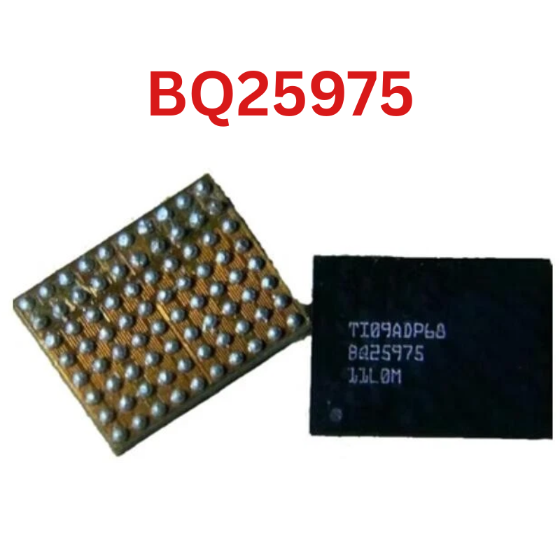
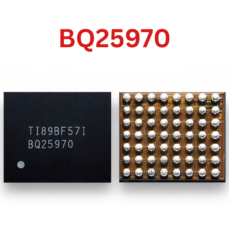
BQ24190 IC
As low as
Rs 0.00
Worldwide shipping · Cash on Delivery
Product Details
1. ARCHITECTURAL OVERVIEW & CIRCUIT OPERATION
The Texas Instruments BQ24190 is a monolithic battery charge management and power-path selector IC:
- Input Power Stage (VBUS / PMID): Accepts 3.9V to 17V from USB or adapter inputs. The input voltage is blocked against reverse polarity and clamped against surges up to 20V. High-frequency bypass is established via PMID capacitors.
- Synchronous Switching Converter (SW / BTST / PGND): Integrates internal high-side and low-side N-channel MOSFETs switching at 1.5 MHz through an external power inductor (typically 1.0 µH to 2.2 µH) to drive the system rail (SYS).
- NVDC-1 Power Path & BATFET (SYS / BAT): Operates between SYS and BAT. When adapter power is present, the system load is powered directly from the input regulator while charging current flows into the battery. If system load exceeds adapter capacity, the BATFET enters supplement mode, drawing power from the battery to assist without rebooting the device.
- Internal LDO (REGN): Produces a steady 6.0V supply (pin 23) used internally to drive the high-side gate driver circuitry. Bypassed with a 4.7 µF ceramic capacitor.
- Thermal Regulation & Monitoring: Automatically throttles charge current if the die temperature reaches 120°C. Monitors dual-pack negative temperature coefficient (NTC) thermistors on TS1 (pin 11) and TS2 (pin 12).
2. 24-PIN VQFN (4x4 mm) PIN ASSIGNMENTS & CRITICAL RAILS
- Pins 1 & 24 (VBUS): Charger input voltage (3.9V - 17V).
- Pins 2 & 3 (PMID): Internal high-side FET drain bypass; must connect to 10 µF / 25V ceramic capacitor to PGND.
- Pin 4 (STAT): Open-drain charging status output (High-Z = charge complete/disabled; Low = charging; 1 Hz blink = fault).
- Pin 5 (SCL): I2C serial clock line (requires external 1.8V / 3.3V pull-up resistor).
- Pin 6 (SDA): I2C serial data bidirectional line (requires external pull-up resistor).
- Pin 7 (INT): Open-drain active-low interrupt output to Application Processor.
- Pin 8 (OTG): USB On-The-Go boost mode hardware enable pin.
- Pin 9 (CE): Charge Enable logic input (Active-low; pull to GND to enable charging).
- Pin 10 (ILIM): Input current limit setting pin (resistor connected to ground).
- Pin 11 & 12 (TS1 / TS2): Battery pack thermistor input divider pins.
- Pins 13 & 14 (BAT): Battery connection to positive terminal of Li-ion cell.
- Pins 15 & 16 (SYS): Regulated system voltage rail (powers the main PMIC and device).
- Pins 17 & 18 (PGND): Power ground returns for synchronous low-side FET.
- Pins 19 & 20 (SW): Phase switching node connected to external inductor.
- Pins 21 & 22 (BTST): High-side bootstrap capacitor terminal connected via 0.047 µF - 0.1 µF capacitor to SW.
- Pin 23 (REGN): Internal 6.0V LDO gate drive output; requires 4.7 µF capacitor to GND.
- Exposed Pad (EPAD): Center ground slug providing thermal dissipation and internal substrate grounding.
3. HARDWARE DIAGNOSTICS & FAULT DETECTION
Cold Impedance / Diode Mode Testing (Red probe on PCB ground, Black probe on test point):
- VBUS (Pins 1, 24): Expected normal drop ~0.500V - 0.620V. (0.000V = dead short on input TVS, filtering capacitor, or internal input FET).
- PMID (Pins 2, 3): Expected normal drop ~0.450V - 0.550V. (Must closely track VBUS when input FET is healthy).
- REGN (Pin 23): Expected normal drop ~0.500V - 0.580V. (0.000V indicates blown internal 6V LDO regulator; IC replacement mandatory).
- SYS (Pins 15, 16): Expected normal drop ~0.350V - 0.450V.
- BAT (Pins 13, 14): Expected normal drop ~0.380V - 0.480V.
- SW (Pins 19, 20): Expected normal drop ~0.400V - 0.500V.
- I2C Bus (SDA / SCL): Expected normal drop ~0.450V - 0.550V. If one line shows "OL", the trace to the pull-up resistor or AP is broken.
Live Voltage Analysis (With 5V USB charger connected):
- Check VBUS: Must measure steady 5.0V - 5.2V.
- Check REGN (Pin 23): Must measure steady 6.0V ± 0.2V. If REGN is 0V despite VBUS = 5V, the BQ24190 is internally defective.
- Check SYS (Pins 15, 16): Must measure minimum 3.5V to 4.2V (NVDC minimum system voltage).
- Check BTST (Pins 21, 22): When switching, BTST must sit approximately 5V above the SW node voltage.
4. REQUIRED WORKSHOP TOOLS & CONSUMABLES
- Precision Hot Air Station (Quick 861DW, Atten ST-862D, Sugon 8620DX) with 5.0 mm circular nozzle.
- Micro-soldering iron station (JBC C245/C210 or T12) equipped with a fine knife (K) or chisel tip.
- Universal or dedicated 24-pin 4x4 mm QFN direct-heat reballing stencil (0.5 mm pitch, 0.12 mm thickness).
- Solder alloy: Sn63/Pb37 leaded solder wire (0.3 mm) and Sn63/Pb37 solder paste (183°C melting point).
- Consumables: Rosin-based tacky no-clean flux (Amtech NC-559-V2-TF), high-density copper desoldering wick (1.5 mm width), 99.9% Isopropyl Alcohol (IPA), high-temperature Kapton tape, aluminum foil heat shield.
5. STEP-BY-STEP MICRO-SOLDERING REWORK INSTRUCTIONS
Step 1: Board Securing and Thermal Shielding
- Fix the PCB into a motherboard repair clamp.
- Protect adjacent components: Memory chips (eMMC/UFS), CPU, and plastic battery/FPC connectors within a 2 cm radius must be covered with Kapton tape and an aluminum foil thermal deflector.
- Ensure the battery is disconnected and discharge any residual charge on SYS/BAT capacitors prior to applying heat.
Step 2: Desoldering and Removing the BQ24190
- Dispense a moderate bead of tacky flux around the perimeter of the QFN-24 package.
- Set hot air station to 335°C - 345°C with an airflow rate of 40 LPM.
- Hold the nozzle vertically at a distance of 1.5 cm and move in steady circular passes around the package for 20 to 30 seconds.
- Because the BQ24190 features a large central thermal ground pad (EPAD), ensure heat penetrates through the package body to fully melt the center solder pool.
- Lightly nudge an adjacent passive component to verify solder liquidity.
- Lift the IC vertically with curved tweezers. Never twist or slide the IC to avoid ripping perimeter pads or smearing solder across the center pad.
Step 3: PCB Footprint Dressing & Planarization
- Add fresh tacky flux to the footprint.
- Tin the iron tip (set to 340°C) with leaded Sn63/Pb37 solder and sweep across all 24 perimeter pads and the center ground pad to dissolve high-melting-point lead-free factory solder (SAC305).
- Lay copper desoldering braid flat across the footprint. Lightly sweep the iron tip across the braid without downward force to remove all excess solder.
- CRITICAL: Ensure the central thermal ground pad is completely flat and planar with the outer 24 signal pads. A convex solder dome on the center pad will pivot the IC, lifting perimeter pins and causing open circuits on VBUS, SW, or REGN lines.
- Clean the area thoroughly with 99.9% IPA and an ESD foam swab. Inspect under the microscope for solder bridges or torn mask.
Step 4: New IC Pre-Tinning / Reballing
- Place the replacement BQ24190 IC into the matching QFN-24 (0.5 mm pitch) stencil.
- Spread Sn63/Pb37 solder paste evenly across all 24 outer apertures and the center thermal pad grid. Wipe flush with a clean razor blade.
- Direct hot air at 280°C - 300°C with low airflow (15-20 LPM) until uniform, bright solder spheres form on all pads.
- Allow the stencil to cool for 15 seconds, apply a drop of flux, reflow briefly for 2 seconds to round the balls, and release the IC.
Step 5: Alignment and Reflow Soldering
- Apply a very thin, translucent layer of tacky flux across the logic board footprint. Excess flux will cause the IC to float and skew during reflow.
- Position the BQ24190 onto the footprint, aligning the Pin 1 corner dot with the logic board silkscreen orientation mark.
- Apply vertical hot air at 320°C - 330°C with moderate airflow (30-35 LPM).
- As the solder reaches 183°C, the IC will sink downward and self-align onto the pads via liquid solder surface tension.
- Execute a delicate "tweezer tap" test: lightly touch the corner of the chip with the tip of your tweezers. The chip must immediately snap back into its centered position, confirming that all 24 perimeter pins and the center ground pad are fully molten and wetted.
- Remove heat vertically and let the board remain undisturbed.
Step 6: Post-Rework Verification & Functional Testing
- Allow natural ambient cooling for 3 minutes. Do not spray freeze spray or use compressed air to prevent thermal shock fractures inside the silicon die.
- Clean all flux residue with 99.9% IPA.
- Measure diode mode values across VBUS, PMID, REGN, SW, and SYS to ensure no bridging occurred between the center thermal pad and adjacent perimeter pins.
- Connect the board to a DC power supply or USB power meter.
- Verify USB charging behavior: current should cleanly negotiate from 0.5A up to 1.5A - 2.0A+ depending on battery state, and REGN should measure 6.0V steady, confirming complete restoration of the charging circuit.
You may also like