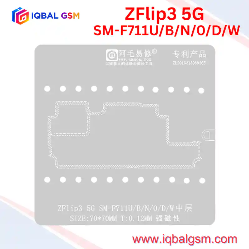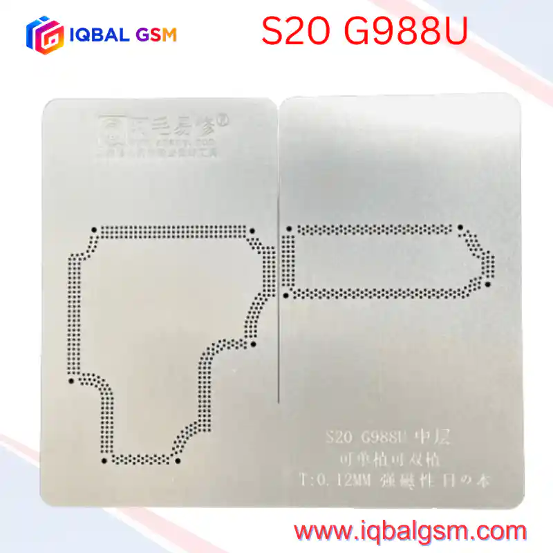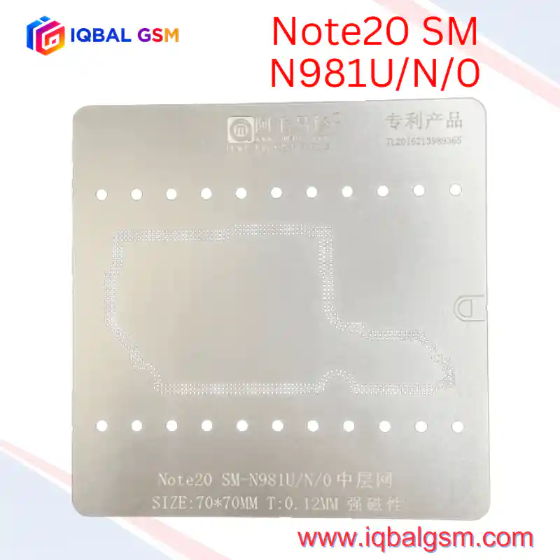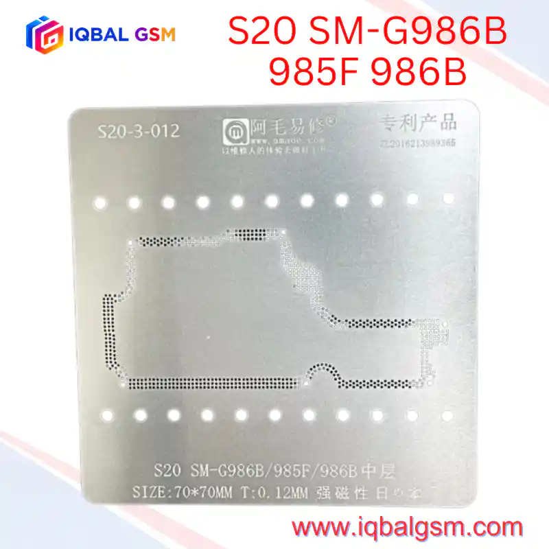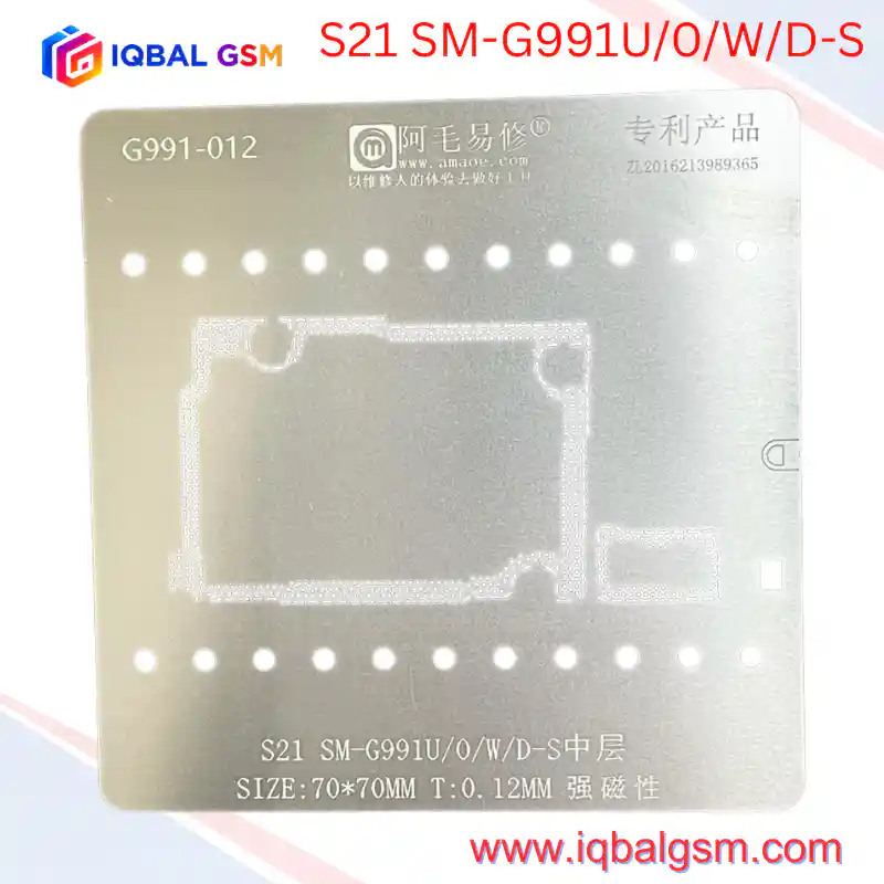

AMAOE S931-012 V3.0 Middle-Layer BGA Reballing Stencil for Samsung Galaxy S25 & S25+ (SM-S931/U/W/0/D & SM-S936 ALL) – 70x70mm, 0.12mm Strong Magnetic
As low as
Rs 1000.00
Worldwide shipping · Cash on Delivery
Product Details
====================================================================================================
AMAOE S931-012 V3.0 (S25 / S25+) MIDDLE-LAYER BGA STENCIL TECHNICAL REWORK MANUAL
====================================================================================================
1. ARCHITECTURAL PURPOSE & DUAL-LAYER PCB DESIGN
----------------------------------------------------------------------------------------------------
The Samsung Galaxy S25 (SM-S931) and Galaxy S25+ (SM-S936) standardize the Qualcomm Snapdragon 8 Elite
(3nm) platform globally across all regional variants, utilizing a compact, vertically stacked dual-layer
(sandwich) motherboard architecture:
* Lower Board (AP / Core Logic Layer): Houses the Qualcomm SM8750-AB Snapdragon 8 Elite SoC, 12GB
LPDDR5X RAM, UFS 4.0 NAND storage, primary PMICs, and display/charging interfaces.
* Upper Board (RF / Modem / Sub-Layer): Houses the Snapdragon X80 5G modem, cellular transceivers,
Wi-Fi 7 / Bluetooth 5.4 RF front-end modules, and antenna switching circuitry.
* Middle Interposer Frame (中层): A peripheral PCB wall populated with high-density, multi-row
staggered copper interconnect pads bridging power rails, MIPI lines, PCIe/RF signals, and ground
planes between the two stacked PCB halves.
The AMAOE S931-012 V3.0 (70x70mm, 0.12mm thick) strong-magnetic stencil is laser-cut to cover all
S25 (SM-S931/U/W/0/D) and S25+ (SM-S936 ALL) interposer footprints, featuring dedicated rectangular
and stepped clearance cutouts along the lower and upper-right margins for adjacent tall SMD components.
2. KEY STENCIL ENGINEERING SPECIFICATIONS
----------------------------------------------------------------------------------------------------
* 0.12mm Calibrated Thickness: Controls exact solder paste volume per aperture so re-stacked board
halves settle to factory Z-height without cold joints (too thin) or inter-pad solder bridges (too thick).
* Strong Magnetic Alloy (强磁性): Locks firmly onto AMAOE magnetic S25/S25+ positioning platforms
via perimeter alignment pin holes, eliminating lateral shift during squeegee passes.
* V3.0 Component Clearance Cutouts: Precision-punched rectangular relief windows prevent the steel
mesh from lifting over nearby inductors and B2B connectors.
* Universal S25 / S25+ Coverage: Supports both base Galaxy S25 (SM-S931 series) and Galaxy S25+
(SM-S936 ALL) dual-layer logic boards (distinct from S25 Ultra SM-S938 boards).
3. CRITICAL SIGNALS ROUTED THROUGH THE MIDDLE LAYER
----------------------------------------------------------------------------------------------------
Cracked, oxidized, or bridged solder joints along the S25/S25+ middle interposer typically cause:
* Baseband Unknown / No Service / 5G Dropout: Open joints on RFFE clock/data, transceiver IQ lines,
or SIM/eSIM interface lines bridging the AP board to the RF board.
* No Boot / High Standby Current: Squeezed solder balls shorting VPH_PWR / VDD_MAIN rails to adjacent
ground pads during improper board re-stacking.
* Wi-Fi 7 / Bluetooth 5.4 Grayed Out: Interrupted PCIe/UART control lines or missing 1.8V/3.3V RF
power rails across the interposer perimeter.
* Camera / Display / Charging Faults: Broken MIPI, I2C, or USB 3.2 differential lines routed between
the AP logic board and upper-board connectors.
4. STEP-BY-STEP MIDDLE-LAYER REBALLING & RE-STACKING WORKFLOW
----------------------------------------------------------------------------------------------------
A. BOARD SEPARATION & PAD PREPARATION:
1. Place the SM-S931 / SM-S936 motherboard onto a dedicated pre-heating platform set to 175°C–190°C.
2. Once the factory middle-layer solder reaches liquidus, lift the upper RF board vertically using
curved ESD tweezers without applying sideways shear force.
3. Sweep both upper and lower interposer rings with a wide knife-edge soldering iron tip (320°C),
low-melt solder (138°C Bi/Sn alloy), and tacky flux to lower residual lead-free solder melting point.
4. Clean all interposer pads thoroughly with 0.8mm/1.0mm desoldering wick and 99.9% Isopropyl
Alcohol (IPA) until every pad is flat and mirror-bright.
B. STENCIL ALIGNMENT & SOLDER PASTE APPLICATION:
1. Seat the lower/middle-layer PCB onto a magnetic S25/S25+ reballing jig (ensuring adjacent SMD
components align cleanly with the V3.0 stencil cutouts).
2. Position the AMAOE S931-012 V3.0 stencil over the board, aligning the staggered perimeter aperture
ring precisely with the PCB copper pads under a stereo microscope.
3. Apply 183°C Sn63/Pb37 (or 158°C/138°C medium-temp) solder paste across the stencil using a
stiff stainless scraper at a 45-degree angle in one smooth pass.
4. Hold the stencil flat and heat evenly with a hot air gun at 260°C–280°C (low airflow, nozzle
~2cm away) until all paste converts into uniform silver solder spheres, OR lift the stencil
vertically first and reflow the printed paste directly on the board.
5. Inspect every perimeter solder ball under the microscope for uniform height and zero bridges.
C. BOARD RE-STACKING (REJOINING):
1. Apply a thin film of no-clean tacky flux along the opposing board's clean interposer pads.
2. Align the upper and lower halves accurately on the pre-heating platform.
3. Heat at 185°C–195°C (matching the chosen solder alloy) until the upper board settles naturally
by surface tension (apply a gentle 1mm nudge with tweezers to confirm self-centering).
4. Allow the board to cool naturally to room temperature before testing with a DC bench power
supply for shorts on VPH_PWR / VDD_MAIN.
5. POST-REWORK VERIFICATION & BENCH DIAGNOSTICS
----------------------------------------------------------------------------------------------------
* Diode Mode Check: Probe key connector lines (SIM, Display, Charging, RF) in diode mode before
powering on to verify zero open lines (OL) or dead shorts to ground.
* DC Power Supply Boot Test: Connect to a regulated 4.2V DC bench supply; verify zero pre-boot
leakage current and clean boot current progression.
* Full RF & Connectivity Audit: Confirm 5G/LTE signal registration, Wi-Fi 7 / Bluetooth 5.4 MAC
address presence, NFC, and 120Hz Dynamic LTPO AMOLED 2X display output.
====================================================================================================
You may also like