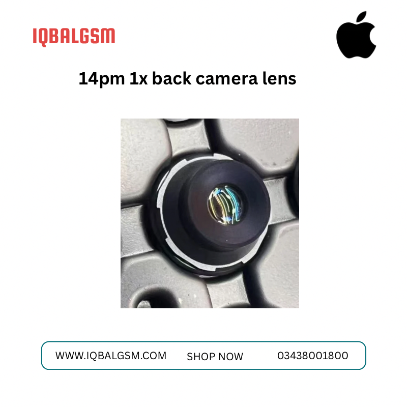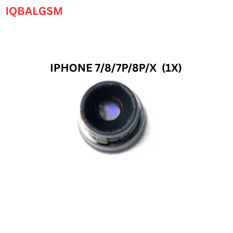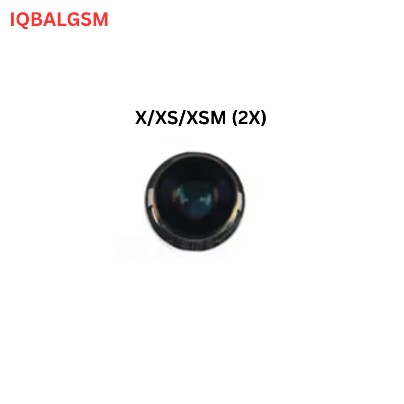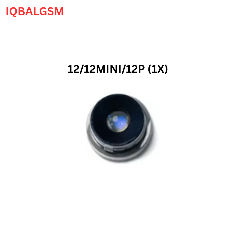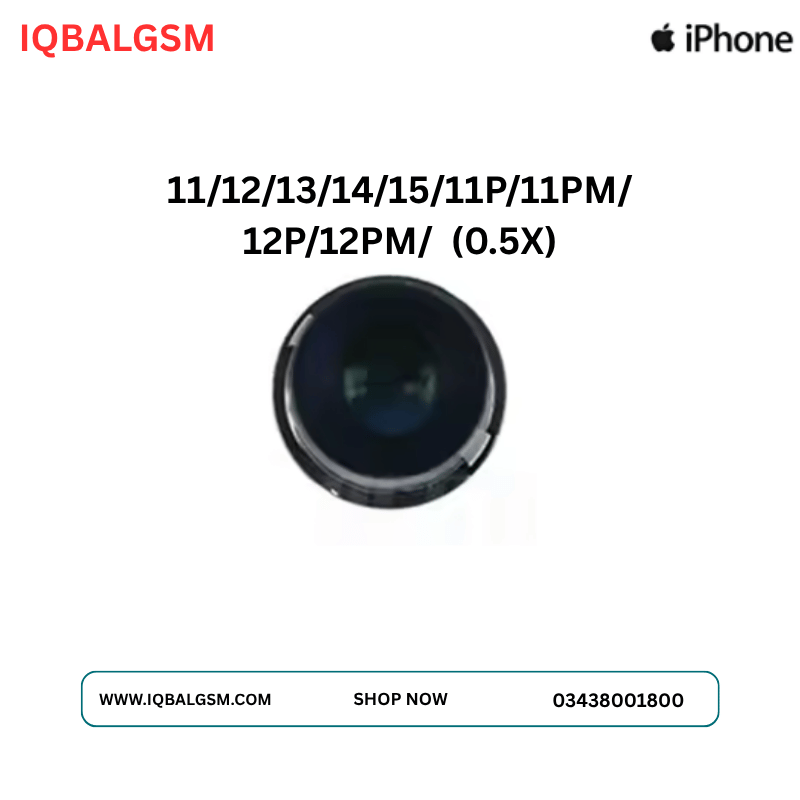

iPhone 16pm 5x Back Camera Blue Lens
As low as
Rs 3900.00
Worldwide shipping · Cash on Delivery
Product Details
================================================================================
IPHONE 16 PRO MAX REAR CAMERA "BLUE LENS" OPTICAL REFURBISHMENT & REWORK GUIDE
================================================================================
1. OPTICAL & ELECTROMECHANICAL ARCHITECTURE OF THE IPHONE 16 PRO MAX CAMERA:
The iPhone 16 Pro Max triple-camera chassis integrates three distinct optical assemblies bonded to dedicated Sony stacked CMOS sensors:
A. 5x Telephoto Tetraprism Sub-Module (120 mm, ƒ/2.8, 12MP):
- Optical Path: Light enters the top barrel lens, passes through the Blue Glass IRCF, and reflects four times inside a folded glass Tetraprism structure before striking a horizontal 12MP CMOS sensor.
- Stabilization & Focus: Driven by a combined 3D Sensor-Shift OIS and autofocus actuator (utilizing Voice Coil Motor [VCM] / Shape-Memory Alloy [SMA] wires) that translates the sensor along X, Y, and Z axes.
- Vulnerability: Because the Tetraprism uses a folded optical path, any micro-scratch or glass shard on the upper entry lens or Blue Glass filter magnifies into severe flare, ghosting, or out-of-focus dark blotches at 5x – 25x zoom.
B. 0.5x Ultra-Wide (13 mm, ƒ/2.2, 48MP) & 1x Main (24 mm, ƒ/1.78, 48MP):
- Standard vertical optical stack: 6-element (0.5x) or 7-element (1x) cylindrical lens barrel threaded/bonded inside a VCM actuator housing, terminated by a flat square/circular Blue Glass IRCF hovering 0.4 mm above the wire-bonded CMOS sensor die.
- Vulnerability: When the exterior rear housing sapphire cover glass breaks, debris falls directly onto the internal Blue Lens. Wiping the lens with alcohol or cotton swabs destroys the soft optical AR coating and forces dust through the perimeter seal onto the CMOS die.
--------------------------------------------------------------------------------
2. THERMAL, SOLVENT & ADHESIVE STRATEGY (CRITICAL SAFETY CONSTRAINTS):
- STRICT SOLVENT PROHIBITION:
* NEVER apply Isopropyl Alcohol (IPA), acetone, or liquid flux remover to the camera module interior or CMOS sensor. Liquid solvents dissolve the black anti-reflective baffle paint inside the barrel, swell the VCM suspension springs, and leave permanent rainbow stains on the Blue Glass IRCF and CMOS micro-lenses.
- Thermal Thresholds:
* Maximum safe temperature for camera module perimeter adhesive softening: 65°C – 75°C.
* Exceeding 85°C permanently warps the internal plastic aspherical lens elements and demagnetizes the Neodymium (NdFeB) OIS magnets.
- Optical Bonding Adhesive Selection:
* Use low-shrinkage, halogen-free black UV-curable optical shadowless adhesive (or high-viscosity black structural sealant) for securing the new Blue Lens barrel to the VCM carrier frame.
--------------------------------------------------------------------------------
3. STEP-BY-STEP CLEANROOM OPTICAL BLUE LENS REPLACEMENT WORKFLOW:
STEP 1: Module Extraction & Exterior Shielding
- Power down the iPhone 16 Pro Max, open the rear glass / display assembly, disconnect the battery, and extract the triple-camera module.
- Immediately seal the two adjacent functional camera lenses and the LiDAR scanner window using residue-free anti-static blue protective tape.
- Mount the triple-camera module into a dedicated CNC aluminum camera holding fixture under a laminar flow hood (or dust-free enclosure) with a stereomicroscope.
STEP 2: Separating the Damaged Blue Lens Barrel
- For 0.5x / 1x Cylindrical Barrels or 5x Entry Barrel:
* Set hot air rework station to 70°C (Airflow: 15% - 20%) and warm the top metal shield rim of the target camera sub-module for 15 seconds to soften the factory black perimeter glue.
* Use an ultra-fine surgical scalpel (No. 11 blade) to score the black epoxy bead around the circumference of the lens barrel where it meets the VCM actuator ring.
* Gently grip the outer lip of the damaged lens barrel with fine non-marring tweezers and lift vertically (or unscrew counter-clockwise if threaded).
* CAUTION: Do not touch or deform the delicate copper/alloy VCM leaf springs surrounding the carrier ring.
STEP 3: Microscopic CMOS Sensor Inspection & Dry Cleaning
- Once the damaged Blue Lens barrel is lifted, the bare Sony CMOS image sensor and its perimeter gold wire-bonds are exposed.
- NEVER touch the gold wire bonds around the perimeter of the CMOS die; breaking a single wire bond permanently kills the camera module.
- Inspect the CMOS surface under 40x magnification using coaxial / oblique green LED inspection lighting to reveal micro-dust particles.
- Remove dust strictly using a specialized **Silicone Gel Sensor Cleaning Stick (Dust-Free Sticky Swab)**:
* First blot the gel tip on clean sticky paper to remove static charge.
* Vertically dab (never drag or wipe) the dust specs off the CMOS glass surface.
* Use a filtered, moisture-free manual air blower bulb for loose perimeter particles.
STEP 4: New Blue Lens Preparation & Seating
- Inspect the replacement Blue Lens (5x / 0.5x / 1x) under the microscope on both the top optical element and bottom blue IRCF glass to confirm zero dust or fingerprints.
- Carefully seat the replacement Blue Lens barrel into the VCM actuator carrier ring, ensuring it sits completely flush against the factory mechanical stop step (preserving exact flange focal distance).
STEP 5: Optical Focus Calibration & UV Tack-Bonding
- Before permanent curing, connect the camera module loosely to a test iPhone 16 Pro Max motherboard and boot into the Camera app.
- Test focus across 0.5x, 1x, and 5x zoom ranges at both macro/near (10 cm) and infinity (> 5 meters) targets.
- If the barrel is adjustable, micro-rotate the lens ring until crisp infinity and near autofocus lock are verified.
- Apply four microscopic dots of black UV adhesive at 90-degree intervals around the outer perimeter seam of the lens barrel using a 0.1 mm acupuncture needle.
- Cure with a 365 nm UV lamp for 20 seconds, then apply a continuous light-blocking black seal around the seam to prevent light leaks.
--------------------------------------------------------------------------------
4. BOARD-LEVEL DIAGNOSTIC MATRIX & CONNECTOR FAULT SIGNATURES:
A. Camera Functional Symptoms vs. Optical / Hardware Root Causes:
┌────────────────────────────────┬────────────────────────────────┬────────────────────────────────────────────────────┐
│ Observed Camera Symptom │ Sub-Module Target │ Root Cause & Corrective Action │
├────────────────────────────────┼────────────────────────────────┼────────────────────────────────────────────────────┤
│ Translucent dark gray/purple │ 5x Telephoto / 1x Main │ Dust particle trapped on internal Blue Glass IRCF │
│ blobs fixed in photo frame │ │ or CMOS sensor surface -> Replace Blue Lens/Clean. │
├────────────────────────────────┼────────────────────────────────┼────────────────────────────────────────────────────┤
│ Milky haze, low contrast, or │ Any Lens (0.5x / 1x / 5x) │ Scratched AR coating or cracked Blue Glass IRCF -> │
│ severe streak flare at night │ │ Replace Blue Lens barrel assembly. │
├────────────────────────────────┼────────────────────────────────┼────────────────────────────────────────────────────┤
│ Bright neon pink/magenta dots │ CMOS Sensor Silicon │ Permanent laser burn on Sony CMOS photodiodes -> │
│ or lines in fixed position │ │ Blue Lens swap will NOT fix; requires CMOS swap. │
├────────────────────────────────┼────────────────────────────────┼────────────────────────────────────────────────────┤
│ Camera shakes violently or │ 5x Tetraprism / 1x OIS │ Damaged OIS Hall sensor, broken VCM spring, or │
│ emits mechanical buzzing │ │ missing 2.8V OIS driver power rail. │
├────────────────────────────────┼────────────────────────────────┼────────────────────────────────────────────────────┤
│ Black screen when switching │ Logic Board / Flex Cable │ Open MIPI CSI-2 differential line, missing LDO │
│ to 5x or 0.5x zoom │ │ power rail (1.2V/1.8V/2.8V), or I2C bus fault. │
└────────────────────────────────┴────────────────────────────────┴────────────────────────────────────────────────────┘
B. Cold Diode-Mode Board Connector Reference Values (Red Probe on GND, Black on FPC Pin):
- MIPI CSI-2 High-Speed Differential Data & Clock Lanes (4-Lane D-PHY / C-PHY per Camera):
* Expected Diode Drop: 0.380V – 0.460V (All positive/negative pairs must match within +/- 0.005V).
* Fault Signature: "OL" indicates torn flex or cold solder joint on B2B connector; 0.000V indicates ESD array short.
- Camera Power Supply Rails (PMIC / Camera Sub-PMIC LDO Outputs):
* VDD_CAM_AVDD (2.8V – 2.9V Analog CMOS Supply): 0.450V – 0.540V
* VDD_CAM_DVDD (1.05V – 1.2V Digital Core Logic): 0.310V – 0.390V
* VDD_CAM_IOVDD (1.8V I2C & Control Interface): 0.460V – 0.530V
* VDD_AF_OIS (2.8V – 3.0V VCM / Tetraprism Actuator Supply): 0.440V – 0.520V
- Control & Synchronization Lines:
* I2C_CAM_SCL / SDA (Bi-directional Control Bus): 0.480V – 0.560V (Pulled up to 1.8V via 2.2k ohm resistors).
* CAM_CLK (24 MHz Reference Clock from SoC): 0.410V – 0.480V.
* CAM_RESET_N / SHUTDOWN: 0.470V – 0.550V.
================================================================================
You may also like