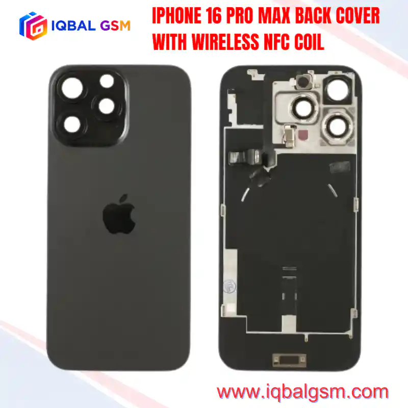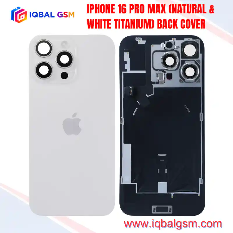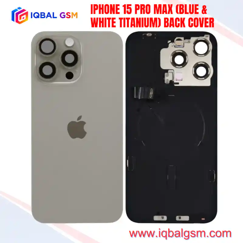

IPHONE 15 PRO MAX (NATURAL & BLACK TITANIUM) BACK COVER
As low as
Rs 0.00
Worldwide shipping · Cash on Delivery
Product Details
====================================================================================================
IPHONE 15 PRO MAX (NATURAL & BLACK TITANIUM) BACK COVER REPAIR & WORKSHOP BENCH MANUAL
====================================================================================================
1. STRUCTURAL ARCHITECTURE & SUB-ASSEMBLY INTEGRATION
----------------------------------------------------------------------------------------------------
The iPhone 15 Pro Max marked Apple's breakthrough transition from legacy bonded-glass housings to a
fully modular, rear-opening chassis architecture. The back glass serves as an independent structural
sub-assembly that bolts and adheres to the internal Grade-5 Titanium chassis:
* Optical Rear Glass Substrate: Dual-ion exchange toughened frosted matte glass matching OEM Natural
Titanium (industrial grey) and Black Titanium (deep obsidian graphite) surface textures.
* Triple Camera Protection Frame: Integrated anodized camera housing plateau complete with three
optical sapphire lens covers, micro-welded rear bezel rings, and secondary microphone inlet.
* Wireless Charging & Heat Dissipation: Multi-strand Litz copper wire induction coil supporting Qi
and MagSafe wireless charging up to 15W, backed with an anisotropic synthetic graphite thermal
dispersion sheet.
* MagSafe Magnet Array: Sintered NdFeB neodymium Halbach magnet ring plus orientation magnet, providing
secure mechanical attachment for MagSafe chargers, car mounts, and battery accessories.
* Sensor & Flash FPC Harness: Flexible printed circuit incorporating the rear True Tone LED flash module,
rear-facing ambient noise-canceling microphone, and high-frequency 13.56 MHz NFC polling antenna.
2. LOGIC BOARD INTERCONNECT & BUS ARCHITECTURE
----------------------------------------------------------------------------------------------------
The integrated back cover harness connects to the central logic board via a high-density board-to-board
(B2B) FPC connector secured beneath a laser-cut stainless steel EMI bracket:
* WPC_VREC / BAT_VCHG: Rectified DC voltage rail from the wireless power receiver IC to the main charging
management circuit (supporting 5V–12V dynamic step-down conversion).
* NFC_ANT_P / NFC_ANT_N: Differential RF signal lines running from the NXP secure NFC controller chip,
governing Apple Pay transactions, Express Cards, and MagSafe accessory handshake recognition.
* FLASH_STROBE_DRV / TORCH_EN: High-current pulsed LED strobe line driven by the dedicated LED flash driver
IC for photography illumination and continuous flashlight operation.
* MIC_REAR_DATA / MIC_REAR_CLK: High-resolution digital audio bus feeding the secondary spatial audio
recording and wind-noise reduction pipeline into the A17 Pro audio DSP.
* NTC_THERMAL_SNS: Embedded negative temperature coefficient (NTC) thermistor monitoring rear enclosure
temperature to dynamically throttle wireless charging current and protect lithium polymer battery health.
3. COMMON FAILURE MODES OF DAMAGED OR LOW-GRADE REAR PANELS
----------------------------------------------------------------------------------------------------
* MagSafe Alignment & Charging Dropout:
Inferior aftermarket back glasses often omit the magnetic Halbach array or use low-grade ferrite
rings, resulting in weak magnetic latching, excessive charging heat, or dropped Qi connections.
* Flashlight & Rear Mic Inoperability:
Tearing or micro-fracturing of the delicate right-hand flex neck during careless glass prying disables
the rear camera flash and causes muffled sound or static in video recording.
* NFC / Apple Pay Communication Timeout:
Damaged antenna traces or misaligned coil grounding shields prevent NFC point-of-sale terminal reads
and disable battery pack identification pop-ups.
* Camera Lens Optical Glare / Focus Artifacts:
Low-grade replacement glass lacking anti-reflective (AR) lens coatings results in chromatic aberration,
night-mode lens flaring, or LiDAR autofocus hunting.
4. STEP-BY-STEP WORKSHOP INSTALLATION & REWORK PROCEDURE
----------------------------------------------------------------------------------------------------
A. DEVICE PREPARATION & OPENING:
1. Power off the iPhone 15 Pro Max. Remove the two bottom P2 (0.8mm) Pentalobe screws adjacent to the
USB-C charging port.
2. Heat the rear glass perimeter to 65°C–70°C for 2 minutes using an LCD heating mat or precision
hot air gun to soften the factory structural adhesive.
3. Apply a heavy-duty suction handle to the lower third of the rear glass. Pull upward gently to create
a 0.5mm insertion gap.
4. Insert a thin plastic opening pick (maximum 2mm depth). Slide along the bottom and left edges.
CRITICAL WARNING: The flex cable connecting the rear glass to the motherboard is routed along the
RIGHT edge. Never insert prying picks or metal tools along the right-hand chassis seam!
5. Swing open the back glass from the left side toward the right, book-fold style, at an angle not
exceeding 90 degrees.
B. DISCONNECTION & FRAME PREPARATION:
1. Remove the two Y000 (0.6mm) tri-point screws securing the lower FPC connector retaining plate.
2. Remove the metal bracket using non-conductive ESD tweezers.
3. Disconnect the rear glass flex connector from the logic board using a flat plastic spudger.
4. Thoroughly clean the perimeter titanium frame ledge using 99.9% Isopropyl Alcohol (IPA) and a nylon
brush to remove all residual adhesive tape, glass splinters, and dust.
C. INSTALLATION OF THE PRE-ASSEMBLED BACK COVER:
1. Inspect the new 15PM assembly (Natural or Black Titanium) under bench lighting to verify camera
lens cleanliness. Blow away any particulate using an anti-static air bulb.
2. Connect the FPC connector of the new back cover assembly to the logic board socket until it snaps firmly.
3. Reinstall the metal retaining plate and torque the two Y000 screws evenly.
4. Peel the protective release film from the pre-applied perimeter adhesive gasket.
5. Align the upper camera bezel with the chassis cutout first, then gently lower the entire back glass
into the perimeter frame channel.
6. Clamp the device in a dedicated screen/back cover pressure jig at 25–30 psi for 5–10 minutes to ensure
uniform adhesive wetting and water-resistant sealing.
7. Reinstall the two bottom Pentalobe screws.
5. POST-REPAIR QUALITY ASSURANCE & VERIFICATION CHECKLIST
----------------------------------------------------------------------------------------------------
* Wireless Charging Check: Place phone on a MagSafe charger; confirm immediate graphic lock animation
and stable current draw without thermal cutoff.
* NFC Verification: Scan a contactless payment card or NFC tag against the upper coil to confirm antenna integrity.
* Flash & Video Audio: Launch Camera app, test rear LED flash in photo mode, and record a 10-second video
while speaking from behind the phone to verify rear microphone clarity.
* Mechanical Flushness: Check that all four corners and sides of the glass sit perfectly sub-flush with the
titanium chassis border without protruding edges.
====================================================================================================
You may also like