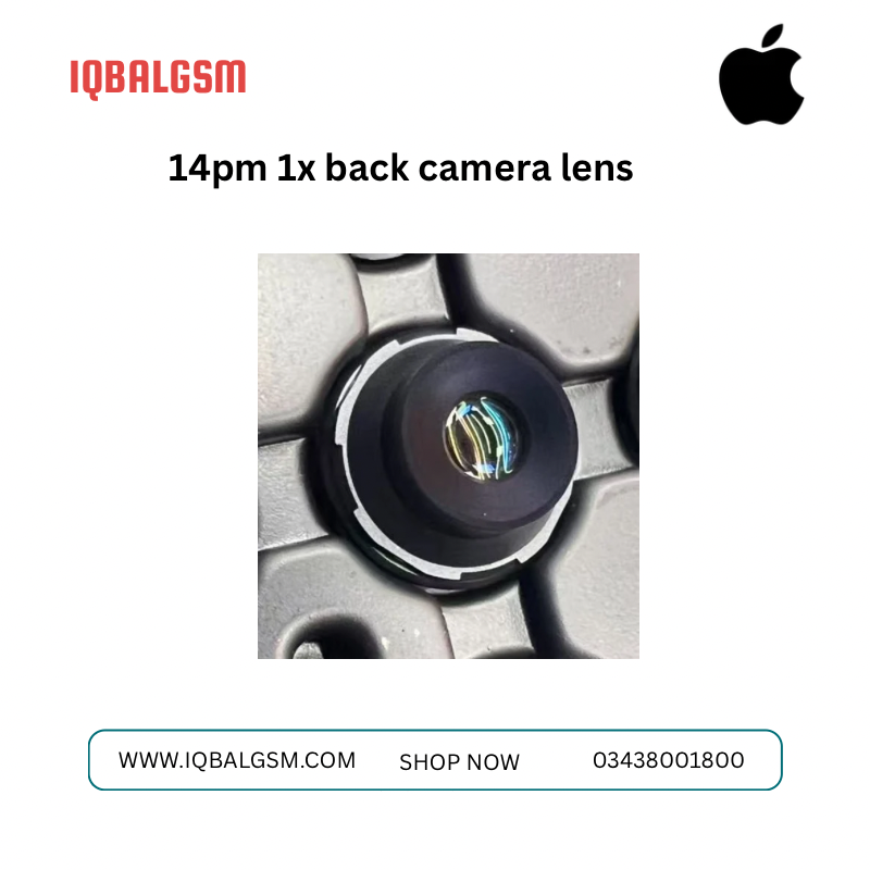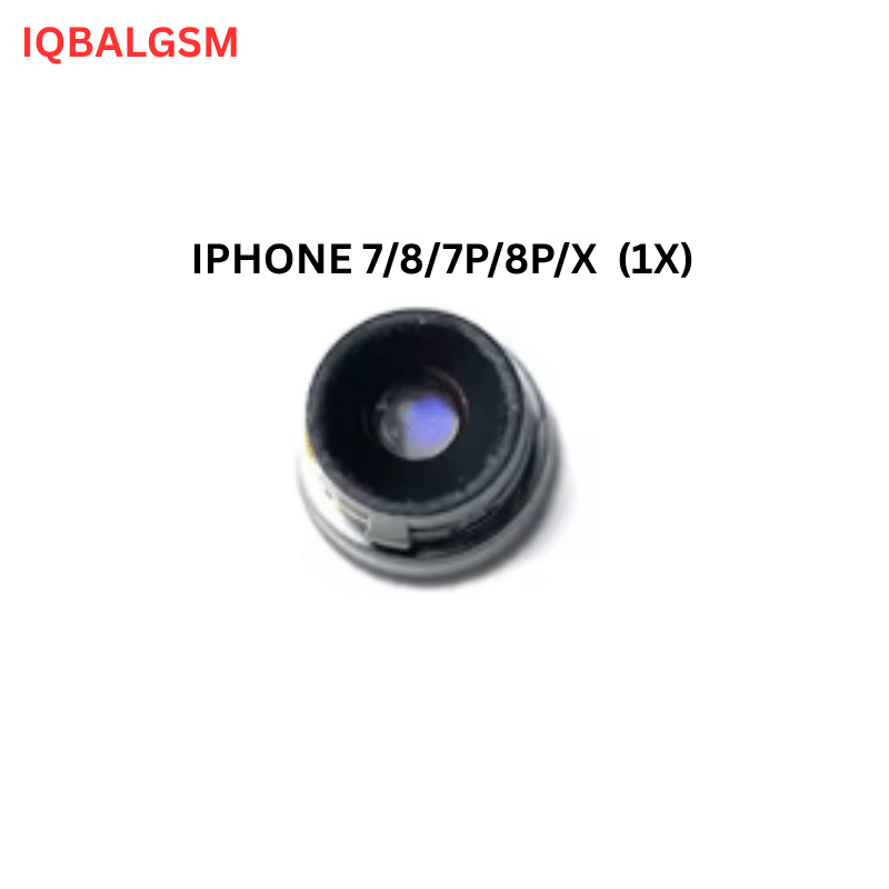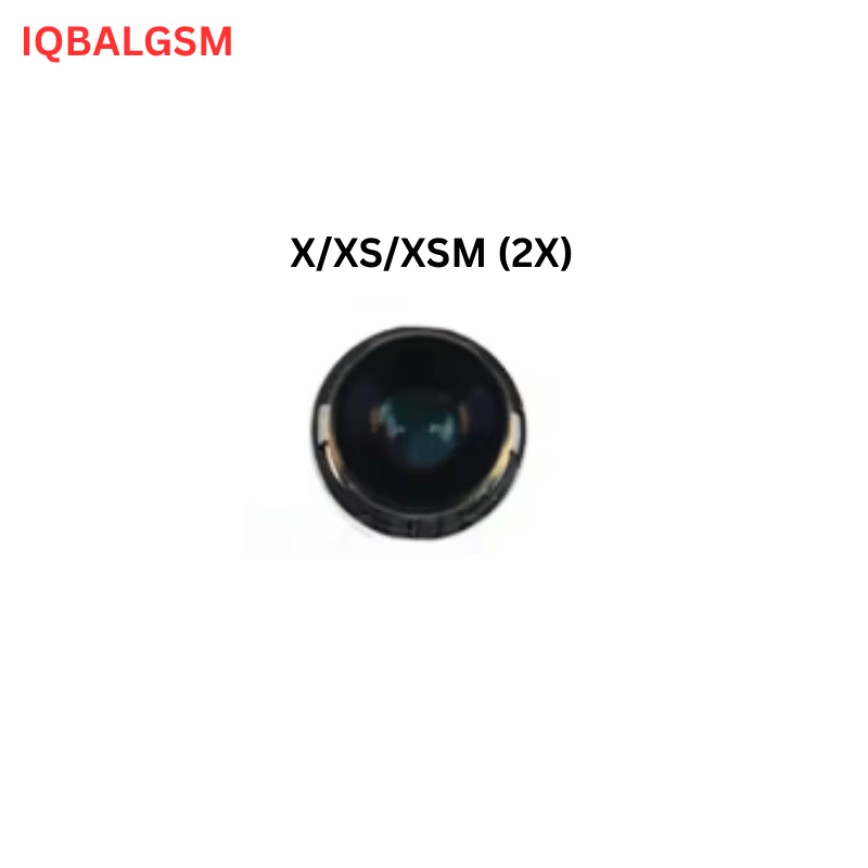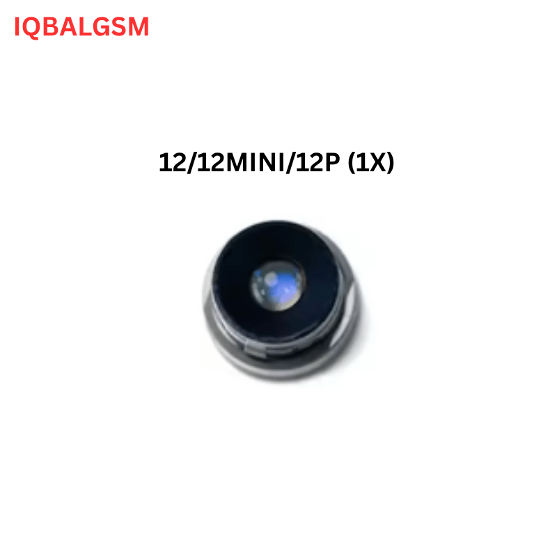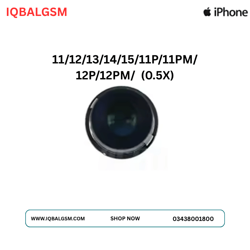

iPHONE 14P/14PM/15P/15PM/16PLUS/ 16P/16PM Back Camera 0.5X Blue Lens
As low as
Rs 900.00
Worldwide shipping · Cash on Delivery
Product Details
================================================================================
IPHONE 14P/14PM/15P/15PM/16PLUS/16P/16PM 0.5X ULTRA-WIDE BLUE LENS REWORK GUIDE
================================================================================
1. OPTICAL & ELECTROMECHANICAL ARCHITECTURE (13MM ƒ/2.2 MACRO AF SYSTEM):
Beginning with the iPhone 14 Pro/Pro Max, continuing through the 15 Pro/Pro Max, and expanding to the iPhone 16 Plus and 16 Pro/Pro Max, Apple standardized the physical barrel geometry of the 13mm ƒ/2.2 Ultra-Wide camera around a closed-loop Autofocus Voice Coil Motor (VCM) capable of 2 cm Macro focusing.
A. Sensor-to-Barrel Alignment & Flange Focal Distance:
- Unlike older fixed-focus 0.5x cameras (iPhone 11/12 series), the 14P–16PM 0.5x sub-module dynamically translates the 6-element Blue Lens barrel vertically along the Z-axis via a magnetic VCM coil and Hall-effect position sensor.
- The Blue Glass IR-Cut Filter (IRCF) is integrated into the bottom lip of the removable lens barrel, suspended ~0.35 mm above the bare Sony CMOS die (Sony IMX633 12MP on 14P–15PM / 16 Plus; Sony IMX972 48MP Quad-Pixel on 16P/16PM).
- Perimeter gold wire bonds connect the top edge of the Sony CMOS die to the underlying ceramic/organic substrate.
B. Failure Mechanics Following Outer Housing Glass Breakage:
- The 0.5x lens features an extreme 120-degree field of view and short focal length (13 mm), giving it a deep depth of field.
- Because of this optical property, any microscopic dust spec, glass splinter, or moisture droplet resting on the internal Blue Glass IRCF or CMOS surface is brought into sharp focus, appearing as dark gray/purple circular spots or spiderweb artifacts across 0.5x photos and Macro mode (automatically engaged when the phone is brought within 10 cm of a subject).
--------------------------------------------------------------------------------
2. THERMAL, CHEMICAL & MECHANICAL SAFETY CONSTRAINTS:
- STRICT LIQUID SOLVENT BAN:
* NEVER use Isopropyl Alcohol (IPA 99%), acetone, contact cleaner, or ultrasonic baths on the camera module or Blue Lens. Solvents strip the multi-layer dielectric AR coating off the Blue Glass, dissolve internal lens element cement, and leave permanent iridescent stains on the CMOS micro-lens array.
- Thermal Ceiling:
* Maximum safe heating temperature for softening the factory barrel-to-VCM perimeter adhesive is 65°C – 75°C.
* Temperatures above 85°C deform the 6P polymeric aspherical lenses (causing permanent peripheral blur/astigmatism) and weaken the VCM leaf springs.
- Electrostatic & Magnetic Precautions:
* Always use non-magnetic titanium tweezers (e.g., 0.1 mm precision tips). Ferrous steel tweezers will snap violently toward the internal VCM magnets, puncturing the CMOS sensor or severing the perimeter gold wire bonds.
--------------------------------------------------------------------------------
3. STEP-BY-STEP CLEANROOM 0.5X BLUE LENS REPLACEMENT PROCEDURE:
STEP 1: Camera Module Isolation & Contamination Shielding
- Extract the rear camera assembly from the iPhone chassis after disconnecting the battery B2B connector.
- Immediately apply dust-free anti-static blue masking tape over the 1x Main and 3x/5x Telephoto lens apertures to prevent cross-contamination during rework.
- Secure the camera module in a dedicated heavy aluminum camera clamping fixture under a laminar flow cleanbench and stereomicroscope (10x – 45x).
STEP 2: Softening & Scoring the Factory Perimeter Epoxy
- Inspect the top ring of the 0.5x sub-module where the black plastic lens barrel joins the VCM actuator ring.
- Set hot air rework station to 70°C (Airflow: 15%) and warm the top rim of the 0.5x barrel for 15 – 20 seconds.
- Using a fresh No. 11 surgical scalpel blade or ultra-thin carbon steel carving blade, gently trace the perimeter groove between the outer VCM carrier ring and the inner 0.5x lens barrel to sever the black elastic sealing glue.
- CRITICAL: Keep blade depth under 0.3 mm. Below the VCM carrier ring sits the delicate copper spider-spring suspension; cutting this spring disables autofocus and causes the lens to rattle.
STEP 3: Damaged 0.5X Blue Lens Extraction
- Grip the top inner collar of the damaged 0.5x barrel using non-magnetic titanium tweezers.
- Gently rotate counter-clockwise while lifting vertically to unseat the barrel from the VCM carrier.
- Remove any residual black adhesive flakes from the VCM inner ledge using a silicone gel sticky swab so the new barrel can seat 100% level.
STEP 4: Bare CMOS Sensor Dry Cleaning
- With the barrel removed, inspect the underlying Sony CMOS die under angled green/white LED illumination.
- Stay strictly away from the perimeter rows of microscopic gold wire bonds.
- Use a fresh, static-dissipated **Silicone Gel Sensor Cleaning Stick**:
* Dab the gel stick vertically onto any dust particles resting on the central active pixel grid.
* NEVER drag, rub, or wipe across the sensor surface.
* Blow off loose debris from the inner walls using a filtered manual air bulb (never canned compressed gas, which spits liquid propellant).
STEP 5: New 0.5X Blue Lens Installation & Optical Axis Alignment
- Inspect the replacement 0.5x Blue Lens under the microscope to verify both the top convex element and bottom flat Blue Glass IRCF are pristine.
- Lower the new 0.5x Blue Lens vertically into the VCM actuator ring until the barrel shoulder rests evenly against the VCM seating step.
- Verify under 20x magnification that the barrel is perfectly horizontal (zero tilt). Even a 2-degree tilt on a 120° ultra-wide lens causes one corner of the image to be blurry (decentering aberration).
STEP 6: Live Focus Verification & UV Curing Seal
- Temporarily connect the camera module to the motherboard and test in the iOS Camera app:
* Check 0.5x wide-angle infinity sharpness across all four corners of the frame.
* Bring an object within 2 cm of the lens to trigger Macro Autofocus and verify rapid, crisp VCM lock.
* Point the camera at a bright white sheet of paper to confirm zero dark spots remain.
- Once verified, apply four micro-droplets of black UV-curable optical adhesive around the barrel-to-VCM seam using a 0.1 mm tungsten needle.
- Cure under a 365 nm UV LED lamp for 20 – 30 seconds, then apply a thin continuous ring of black light-blocking sealant around the perimeter.
--------------------------------------------------------------------------------
4. DIAGNOSTIC MATRIX & BOARD-LEVEL ELECTRICAL REFERENCE VALUES:
A. Post-Rework Optical & Electromechanical Fault Matrix:
┌────────────────────────────────┬────────────────────────────────┬────────────────────────────────────────────────────┐
│ Post-Repair Symptom │ Subsystem Involved │ Root Cause & Corrective Action │
├────────────────────────────────┼────────────────────────────────┼────────────────────────────────────────────────────┤
│ One corner/side of 0.5x photo │ Optical Barrel Seating │ Residual glue flake under barrel shoulder causing │
│ is blurry while center is sharp│ (Decentering / Tilt) │ lens tilt -> Re-lift barrel, clean ledge flat. │
├────────────────────────────────┼────────────────────────────────┼────────────────────────────────────────────────────┤
│ Sharp in Macro (2 cm) but │ Flange Focal Distance (Z-Axis) │ Barrel seated too high (not pressed flush to VCM │
│ blurry at Infinity (> 3 m) │ │ stop) -> Reseat barrel flush into VCM carrier. │
├────────────────────────────────┼────────────────────────────────┼────────────────────────────────────────────────────┤
│ 0.5x zoom option missing in │ CMOS Wire Bonds / I2C Bus │ Broken gold wire bond on CMOS edge or torn flex │
│ Camera app (jumps 1x to 3x/5x) │ │ cable -> Inspect wire bonds or check B2B connector.│
├────────────────────────────────┼────────────────────────────────┼────────────────────────────────────────────────────┤
│ Fixed neon pink/green dot or │ Sony CMOS Pixel Array │ Laser diode burn on silicon photodiodes -> Optical │
│ purple grid lines │ │ Blue Lens cannot fix silicon burn; swap module. │
├────────────────────────────────┼────────────────────────────────┼────────────────────────────────────────────────────┤
│ Faint gray circle still visible│ CMOS Surface / Inner IRCF │ Microscopic dust spec remaining on CMOS center -> │
│ against bright sky/white wall │ │ Lift lens and dab CMOS with clean gel stick. │
└────────────────────────────────┴────────────────────────────────┴────────────────────────────────────────────────────┘
B. Cold Diode-Mode Motherboard B2B Connector Reference (Red Probe on GND, Black on Pin):
- MIPI CSI-2 High-Speed Differential Lanes (0.5x Ultra-Wide 4-Lane Bus):
* Expected Diode Value: 0.380V – 0.460V (All differential pairs must read within +/- 0.005V of each other).
- Power Supply Rails for 0.5x Ultra-Wide Sub-Module:
* PP2V8_CAM_ULTRA_AVDD (2.8V Analog CMOS Supply): 0.450V – 0.540V
* PP1V2_CAM_ULTRA_DVDD (1.2V Core Logic Supply): 0.310V – 0.390V
* PP1V8_CAM_ULTRA_IOVDD (1.8V Digital IO & EEPROM): 0.460V – 0.530V
* PP2V8_CAM_ULTRA_AF (2.8V Macro VCM Actuator Supply): 0.440V – 0.520V
- Control & Clock Signals:
* I2C_CAM_ULTRA_SCL / SDA (Control & Hall Sensor Feedback): 0.480V – 0.560V
* AP_TO_CAM_ULTRA_CLK (24 MHz Master Reference Clock): 0.410V – 0.480V
* AP_TO_CAM_ULTRA_SHUTDOWN_L (Active-Low Reset/Enable): 0.470V – 0.550V
================================================================================
You may also like