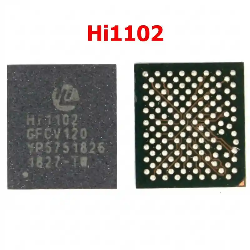
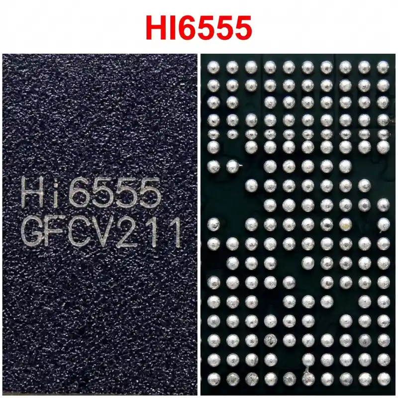
Hi6555 V110 IC
As low as
Rs 0.00
Worldwide shipping · Cash on Delivery
Product Details
1. ARCHITECTURAL OVERVIEW & CIRCUIT SPECIFICATIONS
The HiSilicon Hi6555 V110 is the central master PMIC for Kirin 650/655/658 generation Huawei/Honor smartphones:
- Master Power Sequencing: Directly converts raw battery voltage (V_BATT / VDD_MAIN = 3.6V - 4.4V) into all operational voltage domains. Following power key assertion, the internal state machine sequentially activates core digital rails before releasing the hardware reset (SYS_RESET_N) to the Kirin Application Processor.
- Integrated Buck Regulators:
* VDD_CPU_B: High-current buck rail supplying Kirin big cores (Cortex-A53 high cluster).
* VDD_CPU_L: High-current buck rail supplying Kirin little cores (Cortex-A53 power-saving cluster).
* VDD_GPU: Dynamic voltage buck rail supplying the Mali graphics engine.
* VDD_CORE / MEM: Regulates stable 1.1V / 1.2V power for system cache and LPDDR memory bus.
- Integrated LDO Matrix: Generates over 20 discrete linear regulated supplies, including VDDIO_1V8 (system I/O logic), VDD_EMMC (flash storage logic and memory arrays), VDD_CAM (analog camera rails), and VDD_RF (transceiver baseband bias).
- System Control & Monitoring: Bidirectional SPMI / I2C communication interface for Dynamic Voltage Scaling (DVS) and real-time die thermal throttling.
2. HARDWARE DIAGNOSTICS & SYSTEM FAULT ISOLATION
Step 1: Bench Power Supply Current Draw Analysis (at 4.0V V_BATT):
- Primary VDD_MAIN Short: An immediate short (current jumps directly to power supply limit, e.g., 2A - 5A) before pressing the power button points to a shorted internal high-side buck MOSFET or punctured input bypass capacitor on the Hi6555 V110.
- Power Button Pulse Drop (0 mA -> 30 mA -> 0 mA): The PMIC detects the power button press, begins stage-1 power sequencing, detects a short circuit or missing feedback on a secondary buck rail, and immediately enters fault protection shutdown.
- Low-Current Boot Freeze (40 mA - 70 mA): The PMIC initiates core rails, but one secondary rail (e.g., VDD_MEM or VDDIO_1V8) fails to reach nominal voltage, causing the CPU to hang indefinitely in boot ROM without starting kernel execution.
Step 2: Passive Diode Mode Testing (Red probe on Ground, Black probe on test point):
- Locate the ring of power inductors and SMD capacitors surrounding the perimeter of Hi6555 V110:
* V_BATT / VDD_MAIN Input Capacitors: Expected normal diode drop ~0.380V - 0.480V. (0.000V indicates dead short on main power plane).
* CPU Big / Little Inductor Phase Nodes: Expected normal diode drop ~0.080V - 0.180V (very low impedance is normal for CPU core lines, but 0.000V indicates a dead short).
* GPU Inductor Phase Node: Expected normal diode drop ~0.100V - 0.220V.
* Core / Memory Inductor Phase Node: Expected normal diode drop ~0.250V - 0.380V.
* VDDIO 1.8V Output Line: Expected normal diode drop ~0.420V - 0.520V. (0.000V halts the entire motherboard).
Step 3: Thermal Localization:
- If a primary short exists on VDD_MAIN, connect a DC power supply set to 1.5V (limited to 2.0A) to the shorted rail while inspecting the motherboard with a thermal imaging camera or aerosol freeze spray. If the Hi6555 V110 body illuminates white-hot instantly, internal silicon breakdown is confirmed.
3. REQUIRED TOOLS & REWORK MATERIALS
- Precision Hot Air Rework Station (Quick 861DW, Atten ST-862D, Sugon 8620DX) with 5.0 mm - 6.0 mm nozzle.
- Micro-soldering iron station (JBC C210 / C245 or T12) equipped with a fine knife (K) or chisel tip.
- Stereo inspection microscope (20x - 45x magnification).
- Specialized ultra-thin curved underfill cleaning blade / micro-hook.
- Dedicated HiSilicon Hi6555 / Hi6555 V110 BGA reballing stencil (0.4 mm pitch, 0.12 mm thickness).
- Solder alloy: Sn63/Pb37 leaded solder wire (0.2 mm - 0.3 mm) and Sn63/Pb37 solder paste (183°C melting point).
- Consumables: Rosin-based tacky no-clean flux (Amtech NC-559-V2-TF), high-density copper desoldering braid (1.0 mm to 1.5 mm width), 99.9% pure Isopropyl Alcohol (IPA), high-temperature polyimide (Kapton) tape, aluminum foil heat shield.
4. STEP-BY-STEP UNDERFILL REMOVAL & REWORK PROTOCOL
Step 1: Board Securing and Thermal Shielding
- Fix the Huawei/Honor motherboard securely into an adjustable PCB repair clamp.
- CRITICAL SHIELDING: Huawei motherboards feature Kirin CPUs and eMMC memory chips positioned in close proximity to the Hi6555 Main PMIC or directly on the reverse side of the board. Both are encapsulated with heat-sensitive black epoxy.
- Cover adjacent CPU, memory, and camera FPC connectors with two layers of Kapton tape, topped with an aluminum foil deflector or copper heat-sink coin.
Step 2: Perimeter Underfill Epoxy Removal
- Set the hot air station to 200°C - 220°C with 30 LPM airflow.
- Heat the perimeter edge of Hi6555 V110 for 10-15 seconds to soften the tough factory black epoxy underfill.
- Using an ultra-fine curved underfill scraping knife held at a 45° angle, carefully peel away the perimeter underfill fillet around all four borders of the IC.
- Exercise extreme caution: do NOT dig into the motherboard substrate to avoid severing multi-layer PCB traces or knocking off adjacent 0201 bypass capacitors.
Step 3: Desoldering and IC Extraction
- Apply a generous bead of tacky flux around the chip perimeter.
- Set hot air station to 335°C - 345°C with 40-45 LPM airflow.
- Hold the nozzle vertically (90°) at a distance of 1.5 cm, maintaining smooth circular motions around the chip for 25 to 35 seconds.
- Test solder liquidity by gently nudging an adjacent non-underfilled capacitor.
- When the solder reaches liquidus phase, lift the IC vertically using fine curved tweezers. Never pry, wedge, or twist the IC before the underfill has softened and solder is fully molten to prevent tearing motherboard BGA pads.
Step 4: Footprint Dressing & Underfill Cleanup
- Keep the board slightly warm (~180°C - 200°C) and scrape away remaining underfill glue from between the pads using a flat-edge micro-blade.
- Add fresh rosin flux. Tin the soldering iron tip (set to 340°C) with leaded Sn63/Pb37 solder and sweep across the footprint to dissolve and replace residual factory lead-free alloy (SAC305).
- Lay fine copper desoldering braid flat across the footprint. Lightly glide the iron over the braid without downward force to planarize all pads.
- Clean thoroughly with 99.9% IPA and an ESD foam swab. Inspect under the microscope for missing or torn pads.
- If any active signal pad has torn due to drop stress, scrape the trace, run a 0.02 mm insulated copper jumper wire, form a micro-pad loop, apply UV green solder mask, and cure with a 365 nm UV lamp for 60 seconds.
Step 5: Reballing the Replacement Hi6555 V110
- Ensure the underside of the replacement Hi6555 V110 is clean and completely planar.
- Align the chip into the matching Hi6555 BGA stencil under the microscope.
- Spread Sn63/Pb37 solder paste evenly across all apertures. Scrape flush with a clean razor blade and dry excess moisture with a lint-free cloth.
- Direct hot air at 280°C - 300°C with low airflow (15-20 LPM) from 3 cm distance, gradually moving closer until all apertures melt into uniform, bright 0.20 mm - 0.25 mm solder spheres.
- Allow the stencil to cool for 15 seconds, apply a drop of flux, reflow briefly for 2 seconds to round the balls, and release the IC.
Step 6: Alignment and Reflow Soldering
- Apply an ultra-thin, translucent film of tacky flux across the logic board footprint. Excess flux will cause this large BGA chip to float and misalign during reflow.
- Position the Hi6555 V110 onto the footprint, aligning the Pin 1 corner index dot with the logic board silkscreen orientation mark.
- Apply vertical hot air at 320°C - 330°C with 35 LPM airflow.
- As the solder reaches 183°C, the IC will sink downward and self-align onto the pads via liquid surface tension.
- Execute the "tweezer tap" test: gently tap the corner of the chip body with tweezers; it must instantly bounce back into center alignment.
- Remove heat vertically and keep the board stationary.
Step 7: Post-Rework Verification & Testing
- Allow natural ambient cooling for 3-5 minutes. Never use freeze spray or compressed air to avoid thermal shock cracking inside the silicon die.
- Clean all flux residue with 99.9% IPA.
- Measure diode mode values across all peripheral buck inductors and VDD_MAIN lines to verify zero solder bridging occurred under the array.
- Connect the motherboard to a DC bench power supply; confirm 0.000A standby current prior to pressing the power button.
- Press power button: verify standard dynamic current stepping (100 mA -> 250 mA -> 450 mA -> 700 mA -> 1.1A) indicating proper Kirin CPU initialization and successful boot into the operating system.
You may also like