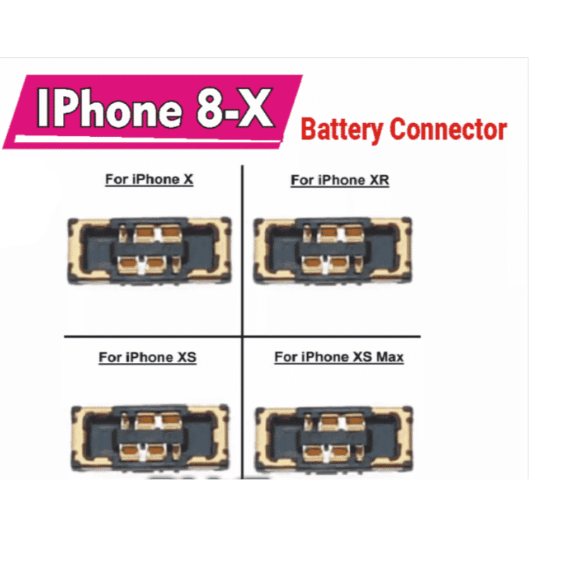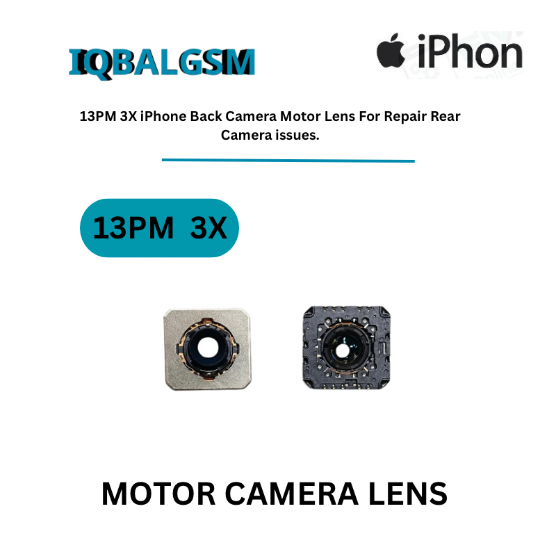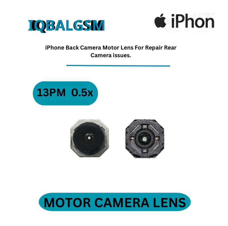

Power Boot Cable FPC Battery Connector Buckle Set
As low as
Rs 0.00
Worldwide shipping · Cash on Delivery
Product Details
================================================================================
MASTER YOUNG IPHONE 6 TO 18 PRO MAX BATTERY FPC BUCKLE TECHNICAL GUIDE
================================================================================
1. SILICON BATTERY MANAGEMENT SYSTEM (BMS) & TELEMETRY PROTOCOLS:
Powering an iPhone motherboard from a DC power supply is fundamentally different from powering an Android device. Apple motherboards enforce strict hardware battery handshakes before allowing complete iOS boot:
A. Four-Pin Battery Terminal Architecture:
- Terminal 1 [VBAT / BATT_VCC]: Direct battery power bus (3.6V – 4.35V). Carries high dynamic current (up to 4.5A during camera flash and peak CPU boost).
- Terminal 2 [GND]: Common chassis ground return.
- Terminal 3 [BATT_SWI / BATT_SDA]: Single-Wire Interface (SWI) / I2C Serial Data bus. Communicates bidirectionally with the Texas Instruments BQ27546 / custom Apple Gas Gauge IC inside the battery protection circuit board (PCM).
- Terminal 4 [BATT_NTC / BATT_SCL]: Negative Temperature Coefficient (NTC) thermistor voltage divider / I2C Serial Clock. Feeds thermal analog/digital telemetry to the Power Management IC (PMIC).
B. The 180-Second (3-Minute) Auto-Restart Loop Mechanics:
- If a technician boots an iPhone using only positive (+) and negative (-) alligator clips, the Application Processor (AP) boots successfully into iOS but cannot read battery temperature or serial cryptography.
- After exactly 180 seconds, the kernel watchdog timer (`watchdogd`) detects a missing battery thermal sensor (`thermalmonitord: thermal sensor 0 missing`), generates a panic log (`panic-full-xxxx.ips`), and forces an immediate hard reboot.
- The Master Young FPC buckles solve this: onboard hardware circuitry emulates the NTC thermistor resistance (10 kΩ reference) and fuel gauge pull-up voltages, allowing the logic board to stay booted indefinitely for diagnostic current analysis.
--------------------------------------------------------------------------------
2. ELECTRICAL SPECIFICATIONS & DC BENCH SUPPLY INTEGRATION:
- Recommended DC Bench Supply Parameters:
* Voltage Setting: 4.00V – 4.20V (Nominal single-cell Li-ion float voltage).
* Current Limit (CC): 3.00A – 4.00A (Setting current limit below 2.0A will cause the phone to brown-out and reset during display backlight or modem power-on).
* Over-Voltage Protection (OVP): Set strictly to 4.50V to protect the primary charging IC (Tigris / Hydra / PMIC).
- High-Current Polyimide FPC Durability:
* Constructed with 2 oz rolled-annealed copper traces capable of continuous 3.5A DC transmission with < 0.05V line drop.
* High-flex polyimide base withstands over 10,000 mating cycles without micro-fracturing internal bus traces.
--------------------------------------------------------------------------------
3. STEP-BY-STEP WORKFLOW FOR MOTHERBOARD POWER BOOT & DIAGNOSTICS:
STEP 1: Buckle Selection & Wire Harness Soldering
- Identify the target device on the Master Young strip (e.g., "16Pro / 16PM" or "13PM / 14PM / 15PM").
- Detach the selected modular buckle cleanly along the laser perforation line.
- Solder red (VBAT +) and black (GND -) insulated silicone lead wires (18 – 20 AWG) to the large gold-plated solder terminals on the buckle tail.
- Connect the opposite wire ends to standard 4 mm banana plugs inserted into the DC regulated power supply.
STEP 2: Motherboard Battery Socket Engagement
- Inspect the female battery connector socket on the iPhone logic board under the microscope to ensure no bent pins or debris.
- Align the Master Young male FPC buckle directly over the socket.
- Press down with balanced finger pressure until a distinct tactile "click" confirms 100% mechanical seating.
- The low-profile connector locks securely, preventing accidental detachment when manipulating the motherboard during probe testing.
STEP 3: Cold Standby Leakage Current Inspection
- Switch on the DC power supply (set to 4.10V / 3.0A).
- DO NOT press the power button yet. Observe the ammeter display:
* Expected Normal Standby Draw: **0.000A** (Zero current).
* Any immediate static current draw before power button press indicates a primary rail leakage fault (see Diagnostic Matrix below).
STEP 4: Triggering Logic Board Boot
- Method A (Hardware Key): Connect a test charging cable (Lightning or Type-C) for 1 second to trigger auto-boot, or short the `BUTTON_TO_PMIC_KEY_L` test point to ground for 1.5 seconds using tweezers.
- Observe the boot current curve on an analog/digital ammeter to diagnose boot stages from iBoot to SpringBoard.
--------------------------------------------------------------------------------
4. BENCH POWER CURRENT DIAGNOSTIC MATRIX & COMMON REPAIR FAULTS:
A. Current Signatures at 4.10V Injection:
┌──────────────────────┬────────────────────────────────┬────────────────────────────────────────────────────────┐
│ Current Reading │ Operational Stage │ Suspected Root Cause & Troubleshooting Target │
├──────────────────────┼────────────────────────────────┼────────────────────────────────────────────────────────┤
│ 2.5A – 5.0A (OCP) │ Immediate current trip upon │ Direct short on primary VDD_MAIN / VDD_BOOST rail; │
│ │ supply switch-on (Pre-boot) │ High-side MOSFET breached; shorted ceramic capacitor. │
├──────────────────────┼────────────────────────────────┼────────────────────────────────────────────────────────┤
│ 0.030A – 0.350A │ Static pre-boot leakage │ Primary rail micro-leakage; defective charging IC │
│ (Static) │ (Pre-boot without pressing pwr)│ (Tigris / Hydra / Kraken) or Audio Codec filter cap. │
├──────────────────────┼────────────────────────────────┼────────────────────────────────────────────────────────┤
│ 0.000A (Dead) │ No response to power trigger │ Open circuit on power key line; dead RTC crystal; │
│ │ │ Main PMIC missing standby LDO (PP1V8_ALWAYS). │
├──────────────────────┼────────────────────────────────┼────────────────────────────────────────────────────────┤
│ 0.035A – 0.065A │ Current freezes instantly upon │ Clock failure (missing 24 MHz / 38.4 MHz AP clock); │
│ (Freeze) │ power key trigger │ Shorted secondary LDO rail; Application Processor dead.│
├──────────────────────┼────────────────────────────────┼────────────────────────────────────────────────────────┤
│ 0.070A – 0.120A │ Current stays fixed in DFU │ Device halts in DFU mode; corrupt NAND flash or blown │
│ (Freeze) │ range │ 0.9V/1.8V/2.5V NAND power rail; broken PCIe trace. │
├──────────────────────┼────────────────────────────────┼────────────────────────────────────────────────────────┤
│ 0.150A -> 0.450A -> │ Infinite cycling restart │ Missing battery data handshake (SWI/NTC open); short │
│ 0.000A │ (Reboots every 3-5 seconds) │ on I2C bus; corrupted NAND bootloader partition. │
├──────────────────────┼────────────────────────────────┼────────────────────────────────────────────────────────┤
│ 0.450A -> 1.80A │ Normal boot curve │ Motherboard healthy; normal transition through kernel │
│ (Fluctuating) │ │ init, display backlight enable, and iOS SpringBoard. │
└──────────────────────┴────────────────────────────────┴────────────────────────────────────────────────────────┘
B. Terminal Diode-Mode Pinout Reference (Red Probe on GND, Black on Battery Socket Pin):
- Pin 1 [VBAT / BATT_VCC]: 0.380V – 0.460V
- Pin 2 [GND]: 0.000V (Chassis Ground)
- Pin 3 [BATT_SWI / SDA]: 0.480V – 0.580V (Pulled up to 1.8V internally; "OL" indicates severed resistor/trace)
- Pin 4 [BATT_NTC / SCL]: 0.460V – 0.550V (Internal thermistor divider reference)
================================================================================
You may also like