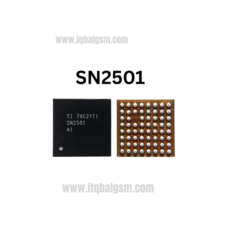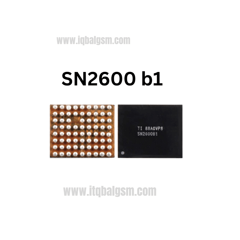

MAX77729X IC
As low as
Rs 0.00
Worldwide shipping · Cash on Delivery
Product Details
--------------------------------------------------------------------------------
SECTION 1: INTERNAL ARCHITECTURE & POWER PATH TOPOLOGY
--------------------------------------------------------------------------------
1. Functional Blocks:
- High-Frequency Synchronous Buck Regulators: Steps down input power to auxiliary logic, memory, and baseband subsystem rails.
- Low-Dropout (LDO) Linear Regulators: Supplies low-noise reference voltages for camera sensors, analog peripherals, and display interface.
- Power Path & Battery Management: Manages current flow between VBUS (charger), VBAT (battery), and VSYS / VPH_PWR (system load).
- I2C Control Interface: Serial communication bus with the Application Processor for dynamic voltage scaling (DVS) and interrupt reporting.
--------------------------------------------------------------------------------
SECTION 2: STEP-BY-STEP MULTIMETER TESTING & DIAGNOSTICS
--------------------------------------------------------------------------------
1. Cold Resistance Testing (Diode Mode Readings - RED probe to GND, BLACK probe on test points):
- VPH_PWR / VSYS Main Inductors & Capacitors (Adjacent to MAX77729X):
* Normal Reading: ~380 mV to 490 mV (Reverse mode must read OL / Infinite).
* Short Circuit Fault: 0.000V confirms burned internal high-side switching FET.
- VBUS Input Filter Capacitor (5V Line from charging port):
* Normal Reading: ~450 mV to 650 mV.
- Surrounding Buck Inductors (Output Coils):
* Low-voltage core coils: ~220 mV to 380 mV.
* Open Circuit Fault: OL on coil output means fractured coil or detached BGA ball.
- I2C Bus Lines (SDA / SCL):
* Normal Reading: ~420 mV to 550 mV on both lines.
2. Hot Voltage Testing (Board Connected to DC Bench Power Supply / Charger):
- Measure VBUS Input Pin: Must read steady +5.0V DC.
- Measure VSYS / VPH_PWR Rail: Must read +3.7V to +4.2V DC.
- Press Power Button:
* Observe current draw on power supply: If current jumps to ~70mA - 120mA and stays frozen (no boot sequence progression), measure the LDO output capacitors around MAX77729X. Missing secondary voltages confirm defective MAX77729X.
--------------------------------------------------------------------------------
SECTION 3: REWORK, DESOLDERING & REBALLING GUIDELINES
--------------------------------------------------------------------------------
1. Safe Removal:
- Redmi Note 11 motherboards have CPU (Snapdragon 680) and UFS memory nearby. Always place high-temperature Kapton tape and thick copper/aluminum heat shields over the CPU/UFS area.
- Apply a drop of quality tacky flux (Amtech NC-559 or Relife RL-422) around MAX77729X.
- Hot Air Settings: 330°C - 340°C with 20% - 25% airflow.
- Heat perpendicularly in small, smooth circles for 10–12 seconds until the BGA balls liquefy completely; lift vertically with fine tweezers.
2. PCB Footprint Preparation:
- Apply 183°C leaded solder wire (Sn63/Pb37) to the motherboard pads at 300°C using a micro-chisel tip to soften lead-free factory solder.
- Gently sweep with 0.6mm / 0.8mm desoldering braid to make the pads completely flat and level.
- Clean the area thoroughly with 99.9% pure Isopropyl Alcohol (IPA) and verify under microscope that no pads are bridged or torn.
3. Reballing & Installation of New MAX77729X:
- Use a dedicated universal PMIC or Xiaomi BGA stencil (Amaoe SAM/MI series, 0.12mm thickness).
- Apply 183°C solder paste smoothly; heat with hot air at 250°C to form uniform spherical micro-balls.
- Apply a micro-thin layer of tacky flux on the cleaned motherboard pads.
- Align the Pin 1 orientation index dot precisely with the white silkscreen dot on the motherboard.
- Solder with hot air at 310°C - 320°C with low airflow (15% - 20%) until the chip self-aligns via surface tension. Give an extremely light side-tap to confirm molten state.
- Allow natural cooling for 2 minutes, clean flux residue with IPA, assemble the board, connect the battery, and power on. Verify standard boot into MIUI/HyperOS and smooth fast-charging current.
You may also like