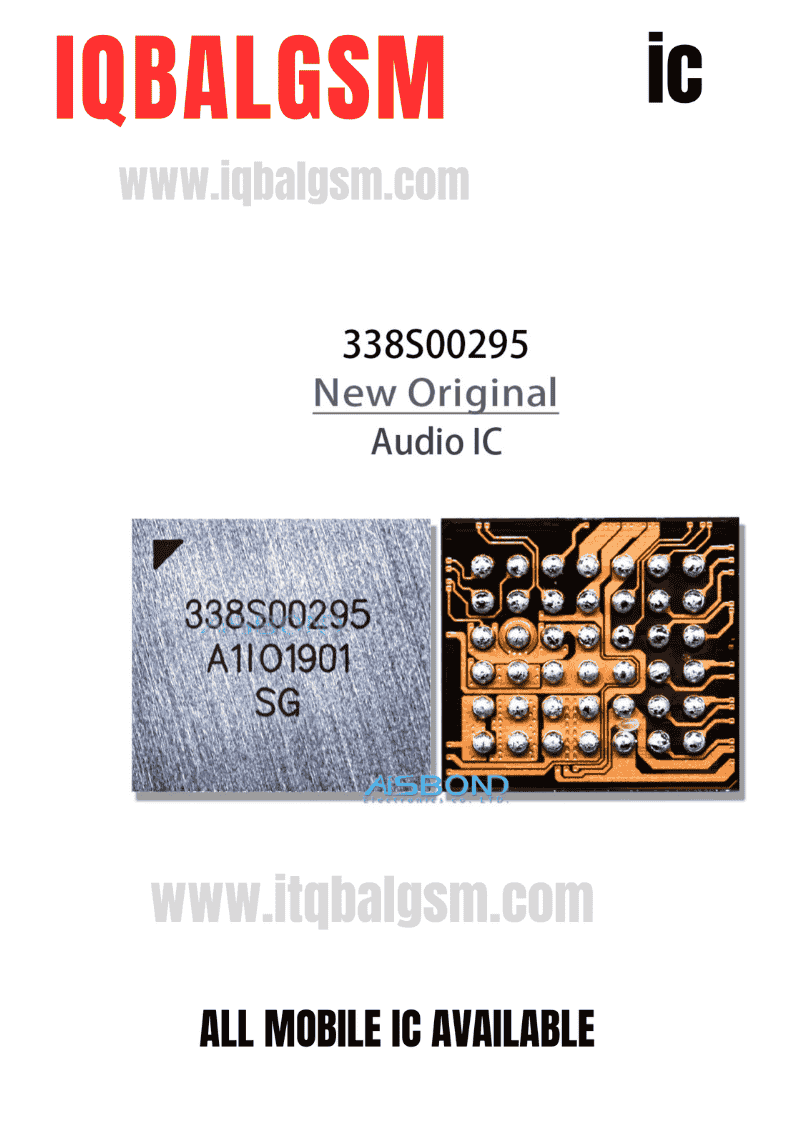
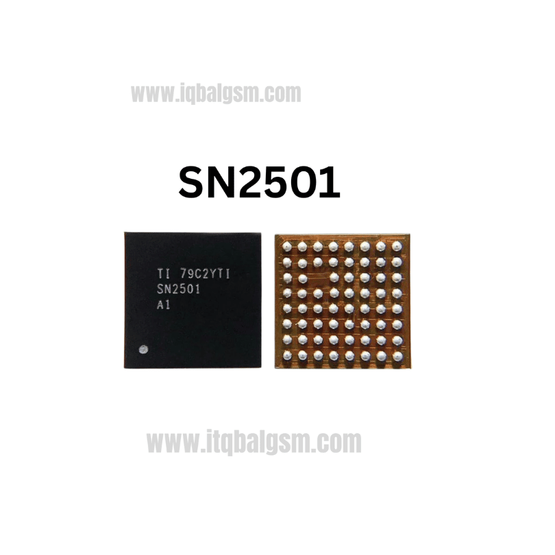
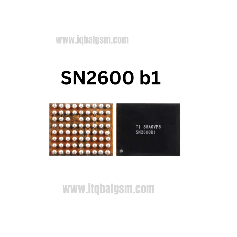
872C IC
As low as
Rs 0.00
Worldwide shipping · Cash on Delivery
Product Details
--------------------------------------------------------------------------------
SECTION 1: INTERNAL ARCHITECTURE & CIRCUIT OPERATION
--------------------------------------------------------------------------------
1. Digital Audio Processing & Control Core:
- Digital Audio Bus: Accepts I2S / PDM digital streams directly from the application processor or dedicated audio codec.
- I2C Command Bus (SDA / SCL): Configures digital volume control, soft-mute profiles, AGC (automatic gain control), and thermal limits.
- Embedded DSP & Sensing: Integrates real-time current and voltage sensing on speaker outputs to dynamically compute voice-coil resistance and cone excursion.
2. Adaptive Boost Converter Subsystem:
- External Power Inductor (typically 1.0µH to 2.2µH high-current saturation inductor): Switches between VBAT/VPH_PWR and the BST/LX switching node.
- Boost Voltage Rail (VBST): Automatically scales from battery level (~3.8V) up to 9.5V dynamically during heavy musical transients to prevent clipping.
- Differential Output Stage (OUTP / OUTN): Bridges directly to the internal transducer through EMI ferrite filtering beads.
--------------------------------------------------------------------------------
SECTION 2: BOARD-LEVEL TROUBLESHOOTING & COMMON FAULT PATTERNS
--------------------------------------------------------------------------------
1. Silent Loudspeaker / No Ringtone Audio:
- Smartphone rings visually, media player progresses normally, but no acoustic output occurs through the speaker grill.
- Cause: Missing VBAT supply rail, blown boost inductor, open-circuit OUTP/OUTN ferrite beads, or an internally fractured 872C chip.
2. Severe Audio Distortion / Clipping at Medium Volume:
- Sound plays quietly, but violently distorts, crackles, or shuts off completely as soon as volume is raised above 50%.
- Cause: Failure of the internal 9.5V boost converter FETs, resulting in rail collapse under speaker load.
3. Complete Logic Board Short Circuit (Dead Phone):
- Connecting the motherboard to a DC bench power supply immediately triggers over-current protection (drawing 2A–4A before power button press).
- Cause: Direct silicon breakdown between the VBAT input bumps and GND within the 872C package.
4. Unresponsive Earpiece / Stereo Channel Imbalance:
- Lower speaker operates normally while top speaker/receiver fails during dual-speaker multimedia playback.
- Cause: Independent failure of the secondary 872C amplifier driving the upper acoustic chamber.
--------------------------------------------------------------------------------
SECTION 3: STEP-BY-STEP MULTIMETER TESTING & DIAGNOSTICS
--------------------------------------------------------------------------------
1. Cold Testing (Diode Mode Readings in mV):
- Set Multimeter to Diode Mode; connect RED probe to logic board GND shield, probe surrounding peripheral components with BLACK probe:
* VBAT / VPH_PWR Input Capacitor: ~350 mV to 450 mV (0.000V indicates a dead short).
* Boost Inductor Terminals: ~350 mV to 450 mV on both input and switching sides.
* Speaker Output Lines (OUTP / OUTN): Measure across output decoupling filter caps; both lines must display symmetrical diode readings (~500 mV to 620 mV, variance <15 mV).
* I2C Bus Pins (SDA / SCL): ~450 mV to 550 mV with pull-up resistor behavior.
2. Hot Testing (Phone Powered On & Audio Ringtone Playing):
- Measure DC Voltages with BLACK probe grounded:
* VBAT Capacitor: Constant battery level (~3.8V to 4.2V DC).
* Boost Output Filter Capacitor: Should dynamically rise to 6.5V–9.5V DC when a loud ringtone or music track is played. If it stays frozen at ~3.8V, the boost stage is defective.
* OUTP / OUTN Lines: Balanced DC bias with active AC RMS voltage during sound playback.
--------------------------------------------------------------------------------
SECTION 4: SOLDERING, REBALLING & REWORK SPECIFICATIONS
--------------------------------------------------------------------------------
1. Chip Removal Procedure:
- Surround adjacent sensitive ICs (CPU, eMMC/UFS memory, and nearby battery/display connectors) with multiple layers of Kapton tape and heat-deflecting aluminum foil.
- Dispense a moderate amount of high-grade tacky rosin flux (e.g., Amtech NC-559-V2) around the 872C chip perimeter.
- Hot Air Station: 330°C - 340°C, 25% airflow using a 3.0mm circular nozzle.
- Heat in a smooth, continuous circular motion for 10–14 seconds. Once all 42 micro solder balls melt, lift the IC vertically using precision micro-tweezers.
2. Motherboard Pad Preparation:
- Add a bead of 183°C leaded solder (Sn63/Pb37) across the footprint to lower the alloy's melting temperature.
- Smoothly sweep 0.8mm desoldering braid at 320°C across the pads without dragging forcefully to ensure zero pad peeling.
- Clean the area thoroughly with 99.9% Isopropyl Alcohol (IPA) and inspect under microscope for pad flatness and absence of solder bridges.
3. Reballing & Installation of New 872C IC:
- Place a dedicated 42-bump BGA stencil over the chip using 183°C medium-temperature solder paste; heat gently at 260°C until uniform spherical balls form.
- Apply a micro-thin layer of tacky flux to the cleaned motherboard footprint.
- Carefully align Pin 1 indicator dot with the motherboard silkscreen white dot.
- Solder at 320°C with 20% airflow; observe the chip naturally settling into position via solder surface tension, and confirm reflow with a microscopic tweezer touch.
- Allow the PCB to cool naturally for 2 minutes, clean with IPA, reassemble the device, and verify clear, loud acoustic output across all speaker and ringer modes.
You may also like