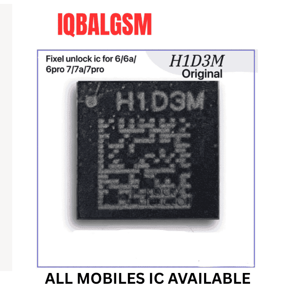
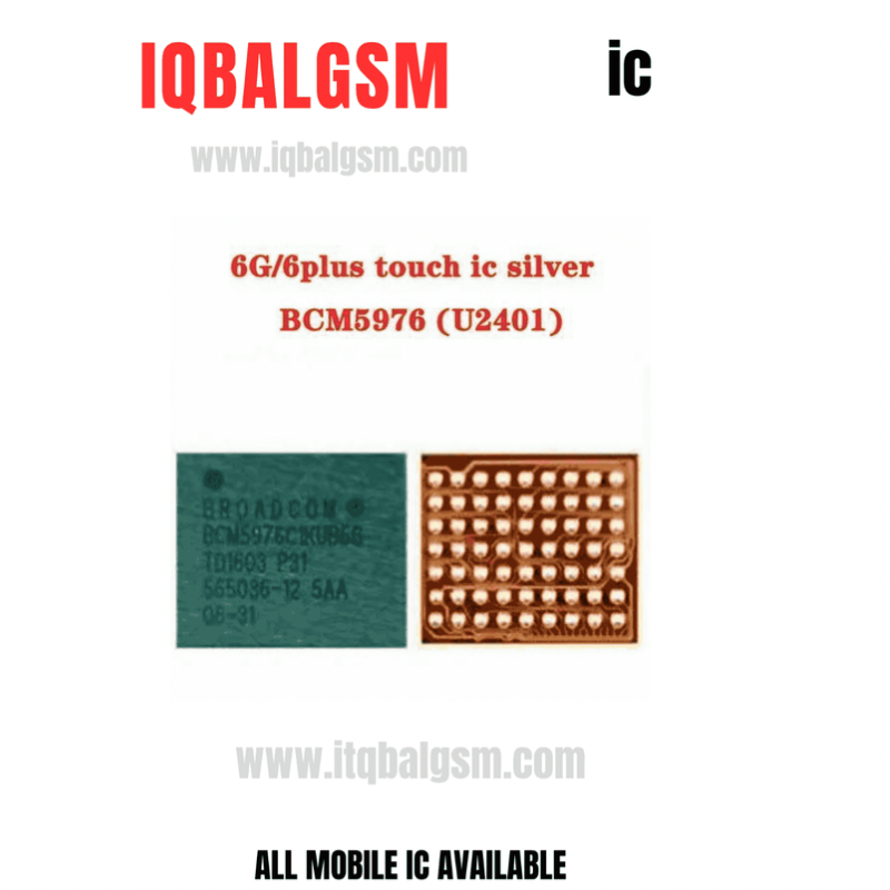
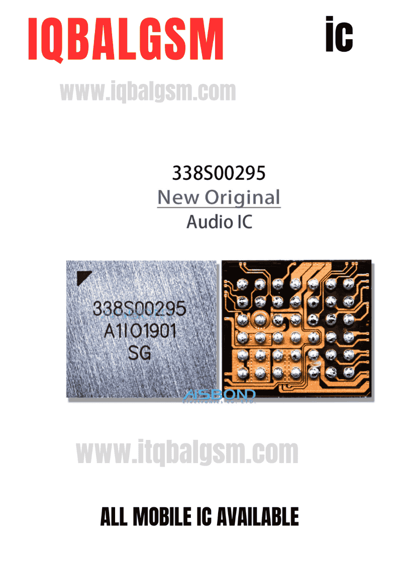
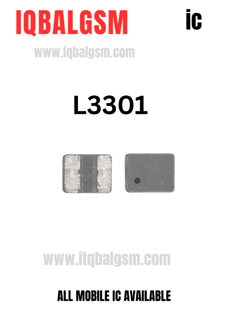
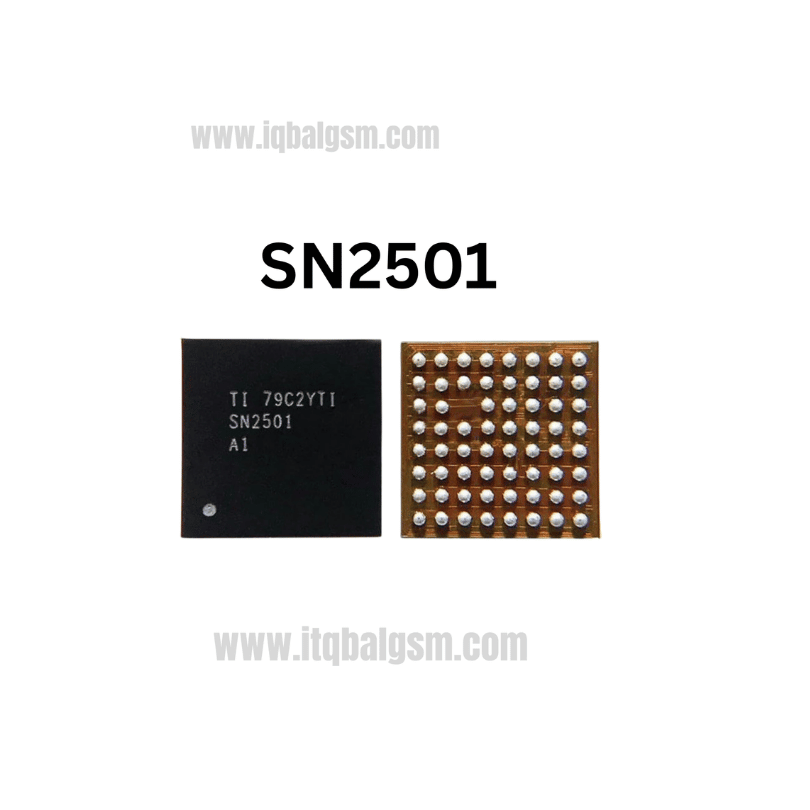
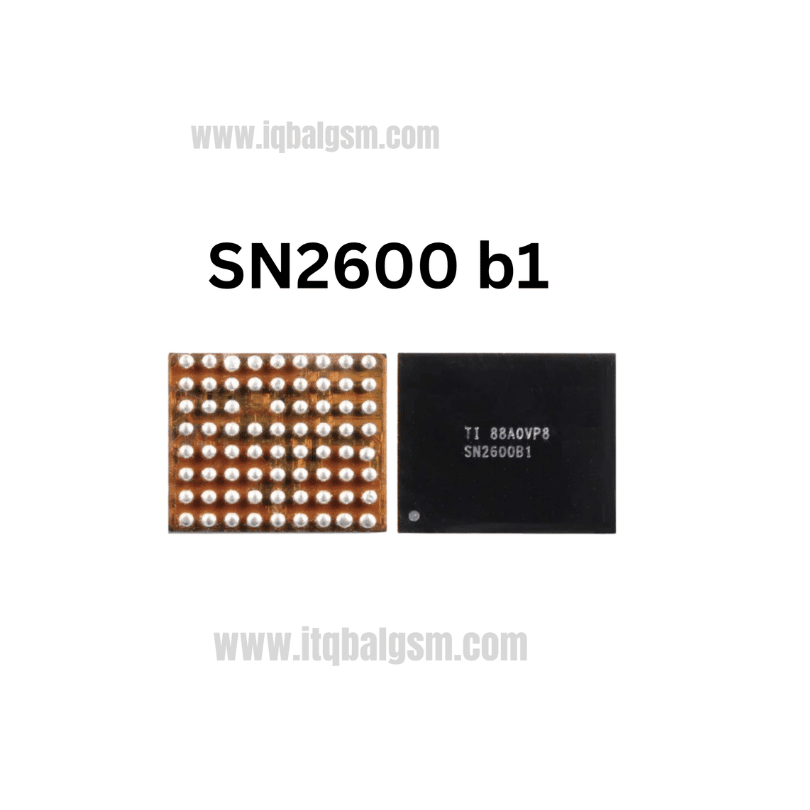
28R5 IC
As low as
Rs 450.00
Worldwide shipping · Cash on Delivery
Product Details
--------------------------------------------------------------------------------
CIRCUIT DIAGNOSTICS & HARDWARE VERIFICATION GUIDE
--------------------------------------------------------------------------------
1. Multimeter Diagnostics (Cold Testing in Diode Mode):
- Place RED probe on logic board ground (metal shielding frame); test lines with BLACK probe:
* Speaker Output Lines (SPK_OUT+ / SPK_OUT-): Decoupling filter line should read healthy diode drop (~500 mV to 650 mV balanced).
* Power Supply Line (VBAT / VPH_PWR / VDD): Should read ~350 mV to 450 mV. (A 0.000V reading confirms an internal short circuit).
* Control / Enable Line (EN / I2C): Should read ~400 mV to 550 mV.
2. Physical IC Inspection & Verification:
- Since wholesale bags often use vendor-specific shorthand, inspect the bare silicon surface of one chip under a microscope:
* If laser-engraved with an alphanumeric silicon code (e.g., AW87xxx, TFA9xxx, CS35Lxx, or specific SMD code), that exact silicon code will pinpoint the pin-to-pin schematic diagram.
3. Soldering & Replacement Guidelines:
- For miniature audio/ringer IC packages:
* Rework Temperature: 320°C - 330°C with 20% gentle airflow.
* Use high-quality rosin flux (Amtech NC-559 or Relife RL-422) and 183°C solder paste.
* Ensure correct Pin 1 orientation dot before applying hot air reflow.
You may also like